Quick Start Instructions
Hooking up the GR 2400 System
The GR 2400 system is very simple to put together.
The basic system consists of:
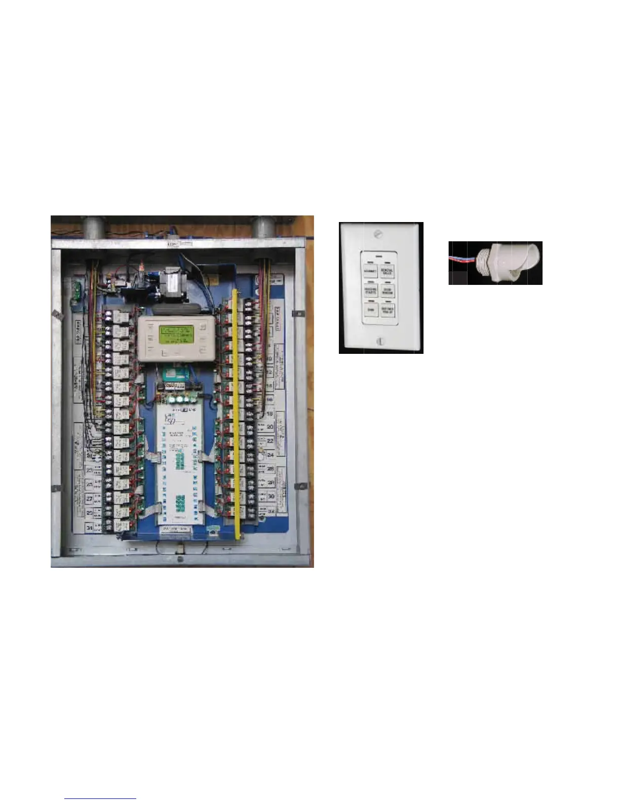
1)The Master Panel like the one on the left, it will have a
Clock Display and usually a modem.
2) A Switch or Switches like the Chelsea switch shown
above.
3) Sometimes there will be a Photocell.
4) Sometimes there will be additional slave relay panels.
They do not have the clock display or the modem in them.
5) Sometimes there will also be other accessories. These
are discussed later in the manual.
All these items are hooked together on a digital bus of
Category 5, four twisted pair data cable.
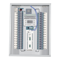
GR 2432 Relay Panel with 32 Relays Rated at 20 amps 277 Vac
Left barrier removed to show complete relay.
Outdoor Photocell
Chelsea 6 Digital Switch
C