FACTORY SETUP MENU
ADDRESSING BUS SCAN
PANEL/SWITCH TYPES
RELAY PROPERTIES
REMOTE SYSTEM MENU
OW NER SETTINGS
ERASE OPTIONS
Additional Features in Clock version 4.16
The Erase Options Menu has been changed:
ERASE OPT IONS
ERASE BY ADDR. BT N
DEFAULT NAMES
ERASE RELAY BOARDS
ERASE CLOCK MEMORY
ERASE BY ADDRESS
One may now erase a card by its address remotely without push-
ing the address button on that card. This is particularly useful
when one does not have a partner to help do the remote button
pushing.
!!! WARNING !!!
PANEL/SWITCH TYPES
MUST BE SET PROPERLY
FOR THIS ADDRESS
BEFORE YOU ERASE !!!
ERASE ADDRESS:
N
PANEL/SWIT CH TYPES
RELAY PROPERTIES
REMOTE SYSTEM MENU
OWNER SETT INGS
ERASE OPT IONS
ADDRESSING BUS SCAN leads
to the Bus Diagnostics menu which
now has additional items.
BUS DIAGNOST I CS
AUTOADDRESSING
READ ADDRESS
BUS SCA N DISPLAY
ERROR STATISTICS
MORE DIAGNOSTICS
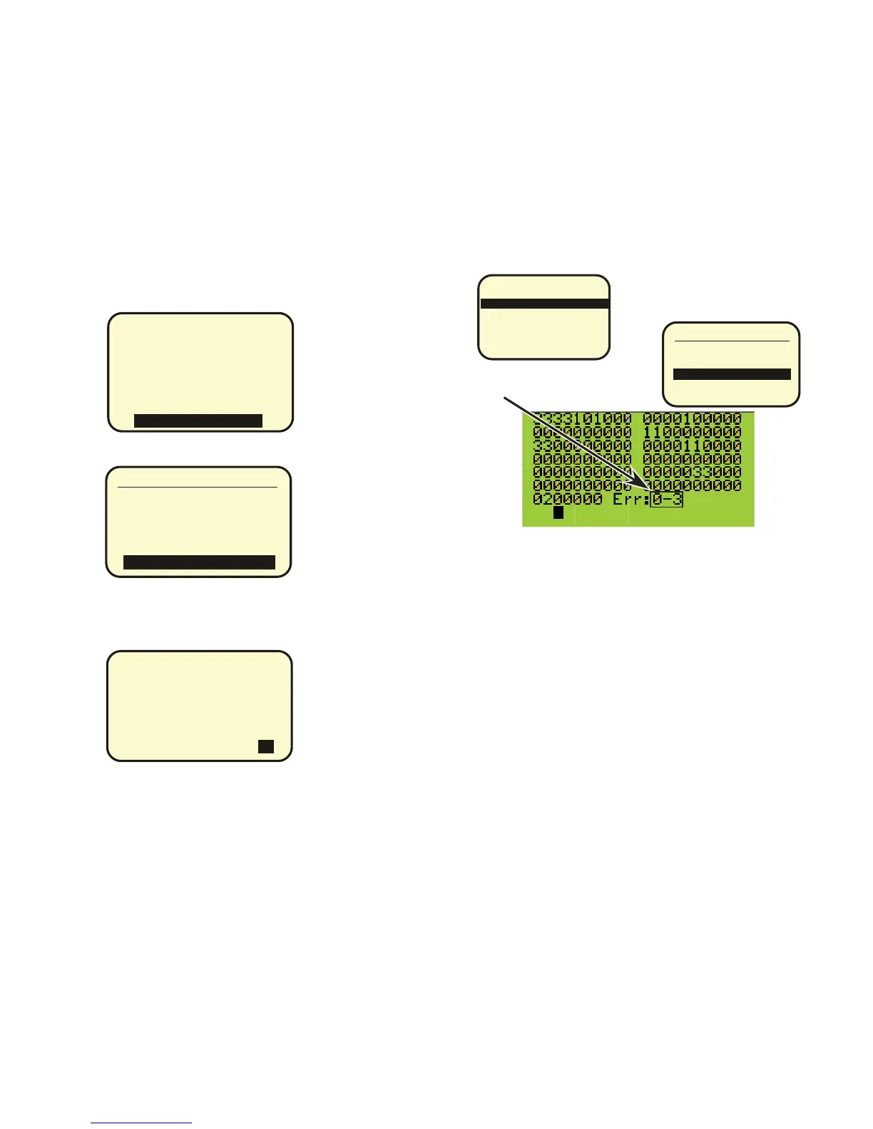
BUS SCAN DISPLAY now has
two sections to the Error field
As before each location on the screen represents an item on the bus. There
are 127 locations for these items. The clock is always at address Zero to
make 128 items. Each 3 represents an 8 relay card or part of a Relay card,
each 1 represents a photocell or switch or a digilink. This screen is consid-
ered to be a “PRESENCE MAP” of the system and shows what is present
and what is not.
The Error count is divided into two sections. The first number is the number
of actual drop offs from the bus. The second number is the number of failed
communications encountered during the bus scan. The Black dot at the bot-
tom is an indicator that shows that 8 items have been scanned each time it
moves. Scanning is done by a “are you there” command. A single bit
response of pulling the bus low is used to speed up the scan.
If a particular address does not respond or an answer is not received the
second counter is incremented and the address is polled again. The lack of
response may be due to a collision with a button being pushed or noise on
the bus or a reflection due to lack of a terminator. If no response if received
on the third poll the item is counted as “dropped” the first number is
incremented and the scan moves on.
The DROP OFFs count starts at zero each time the screen is opened. The
Communication failures are incremented until the clear button is pressed in
the ERROR STATISTICs screen. These counts are also shown by address
in additional screens in the MORE DIAGNOSTICs menu.
Page 45