Adtech CNC Technology Co., Ltd. 12. Hardware interface definition and connection instructions
- 85 -
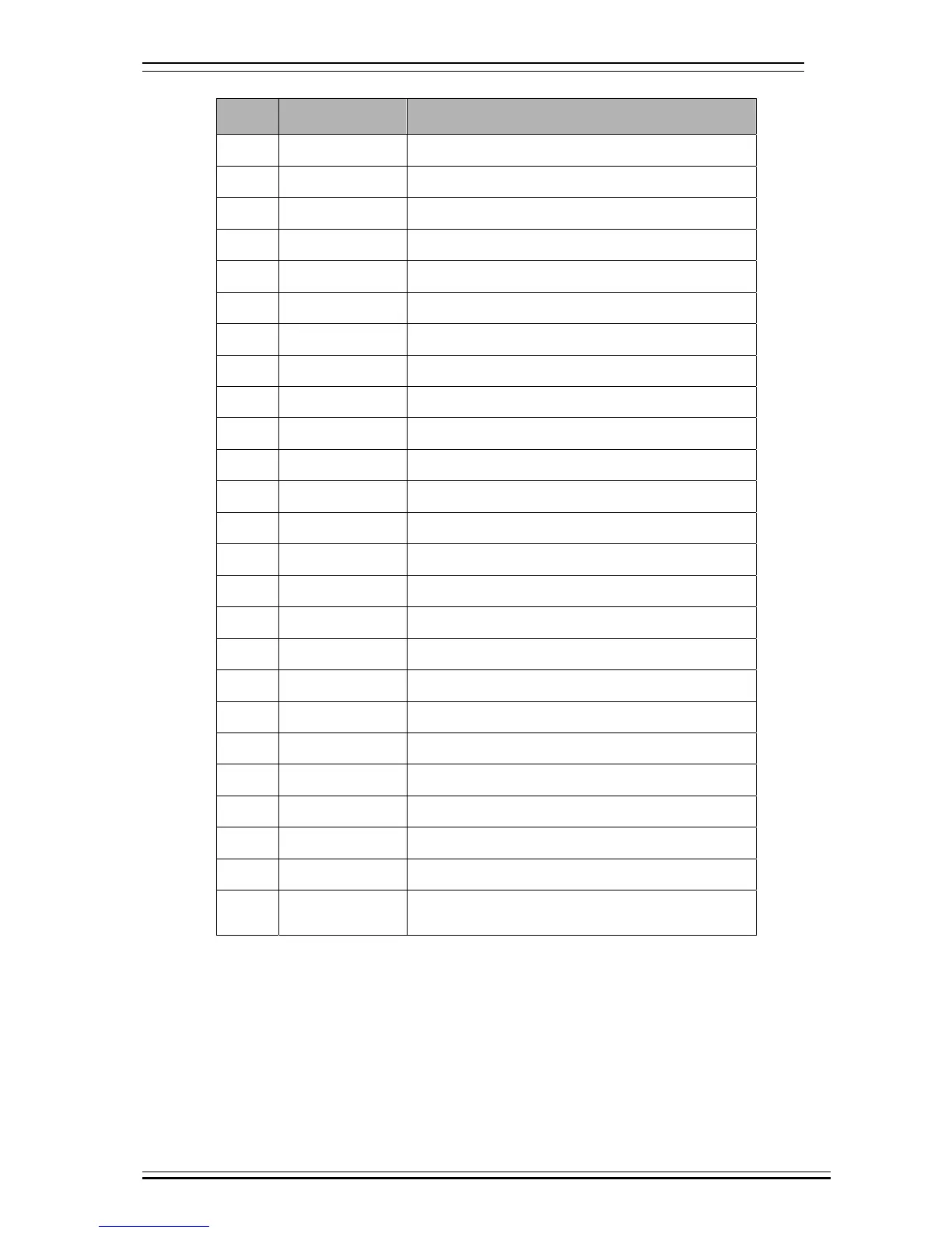
Default input port configuration of L series (lathe)
Wire
No.
Definition Function
1 IN0 X axis zero point
2 IN1 Standby input
3 IN2 Z axis zero point
4 IN3 Standby input
5 IN4 Tool #1 in place test
6 IN5 Tool #2 in place test
7 IN6 Tool #3 in place test
8 IN7 Tool #4 in place test
9 IN8 Tool #5 in place test
10 IN9 Tool #6 in place test
11 IN10 Tool #7 in place test
12 IN11 Tool #8 in place test
13 IN12 Standby input
14 IN13 Standby input
15 IN14 Standby input
16 IN15 Standby input
17 IN16 (XLMT-) X axis negative limit (standby IN32)
18 IN17 (XLMT+) X axis positive limit (standby IN33)
19 IN18
20 IN19
21 IN20 (ZLMT-) Z axis negative limit (standby IN36)
22 IN21 (ZLMT+) Z axis positive limit (standby IN37)
23 IN22
24 IN23
25 INCOM
Input common end INCOM (24V+, 12V+) connects
to internal or external power supply