ADTECH9 Series CNC Maintenance Manual
- 189 -
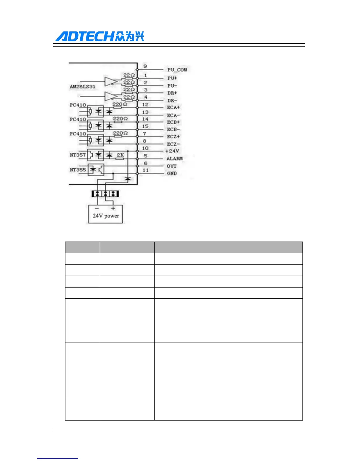
Simple Internal Circuit Diagram for Pulse Output
Wire No. Definition Function
1 PU+ Pulse signal +
2 PU- Pulse signal -
3 DR+ Direction signal +
4 DR- Direction signal -
5 ALM
Servo alarm signal input (CNC96 series X axis: IN66, Y axis:
IN67, Z axis: IN68, A axis: IN69, B axis: IN70) (CNC99,
CNC98 series X axis: I66, Y axis: I67, Z axis: I68, A axis:
I69, B axis: I70, C axis: I71)
6 OUT
Axis alarm reset output signal (CNC96 series X axis:
OUT48, Y axis: OUT49, Z axis: OUT50, A axis: OUT51, B
axis: OUT52) (CNC99, CNC98 series X axis: OUT48, Y
axis: OUT49, Z axis: OUT50, A axis: OUT51, B axis:
OUT52, B axis: OUT53)
7 ECZ+
Encoder phase Z input + (CNC96 series X axis: IN40, Y axis:
IN43, Z axis: IN46, A axis: IN49) (CNC99, CNC98 series X