ADTECH9 Series CNC Maintenance Manual
- 206 -
2 DAOUT2 Analog voltage output (0~10) V
3 GND Internal 24V power grounding
4 GND Internal 24V power grounding
5 GND Internal 24V power grounding
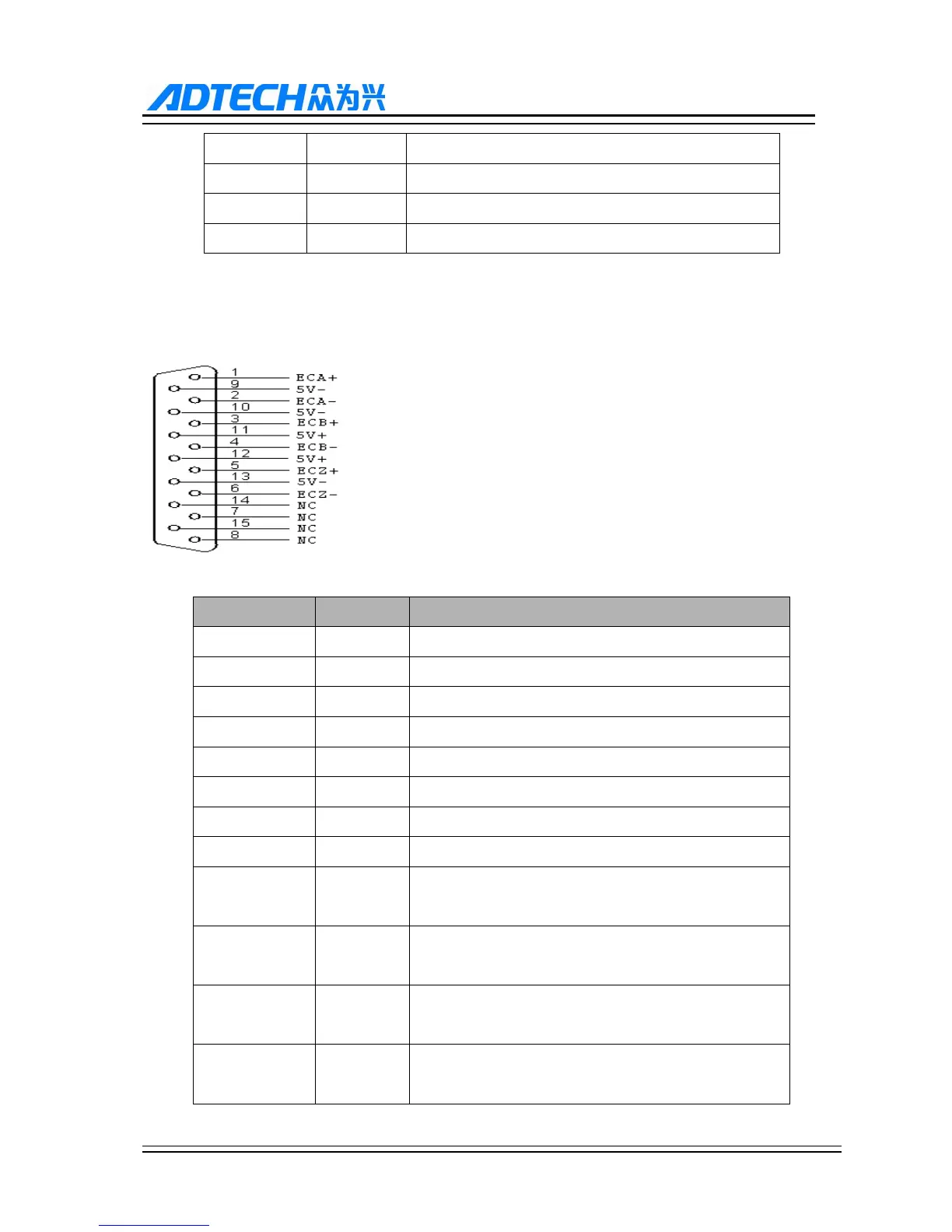
12.2.6. Spindle encoder interface (9640 series XS12)
Spindle encoder interface diagram (9640 series XS12):
The spindle encoder (9 series CNC9640 controller) definition is as follow:
Wire No. Definition Function
1 ECA+ Encoder phase A input +
2 ECA- Encoder phase A input -
3 ECB+ Encoder phase B input +
4 ECB- Encoder phase B input -
5 ECZ+ Encoder phase Z input + (IN76)
6 ECZ- Encoder phase Z input - (IN76)
7 NC Null
8 NC Null
9 5V- Negative end of internal 5V power supply can’t be
connected to external power supply
10 5V- Negative end of internal 5V power supply can’t be
connected to external power supply
11 5V+ Positive end of internal 5V power supply can’t be
connected to external power supply
12 5V+ Positive end of internal 5V power supply can’t be
connected to external power supply