ADTECH9 Series CNC Maintenance Manual
- 190 -
axis: IN72, Y axis: IN73, Z axis: IN74, A axis: IN75, B axis:
IN76, C axis: IN77)
8 ECZ-
Encoder phase Z input - (CNC96 series X axis: IN72, Y axis:
IN73, Z axis: IN74, A axis: IN75) (CNC99, CNC98 series X
axis: IN72, Y axis: IN73, Z axis: IN74, A axis: IN75, B axis:
IN76, C axis: IN77)
9 GND
99 series reference ground, 96 series single-ended to common
terminal
10 24V+
Internally provided 24V power supply, directly connected to
24V power supply of the controller
11 24V-
12 ECA+ Encoder phase A input +
13 ECA- Encoder phase A input -
14 ECB+ Encoder phase B input +
15 ECB- Encoder phase B input -
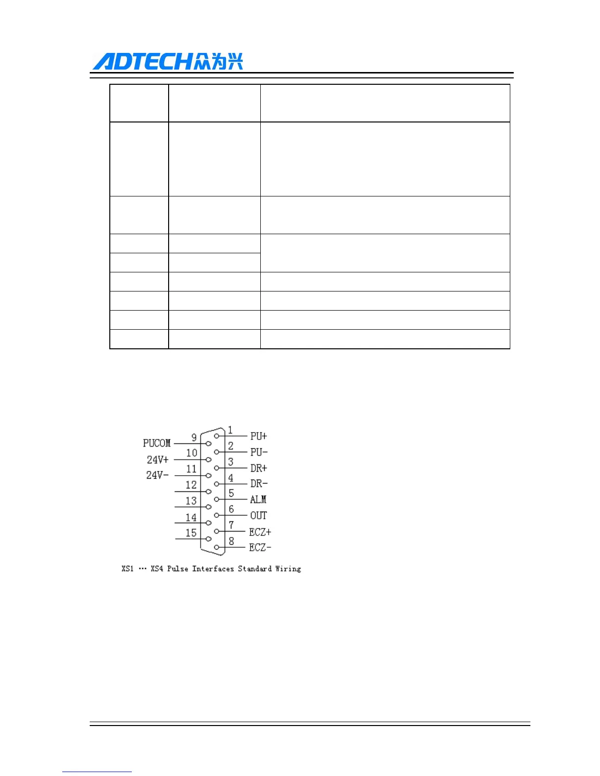
Standard pulse wiring diagram
This wiring is suitable for 96 and 99 series controller
Step motor driver cable to differential input
Adtech CNC driver is used for reference, all of which use differential input mode. This mode has strong
anti-interference and is recommended. Please refer to the figure below for the connection of CNC with step
motor driver and step motor