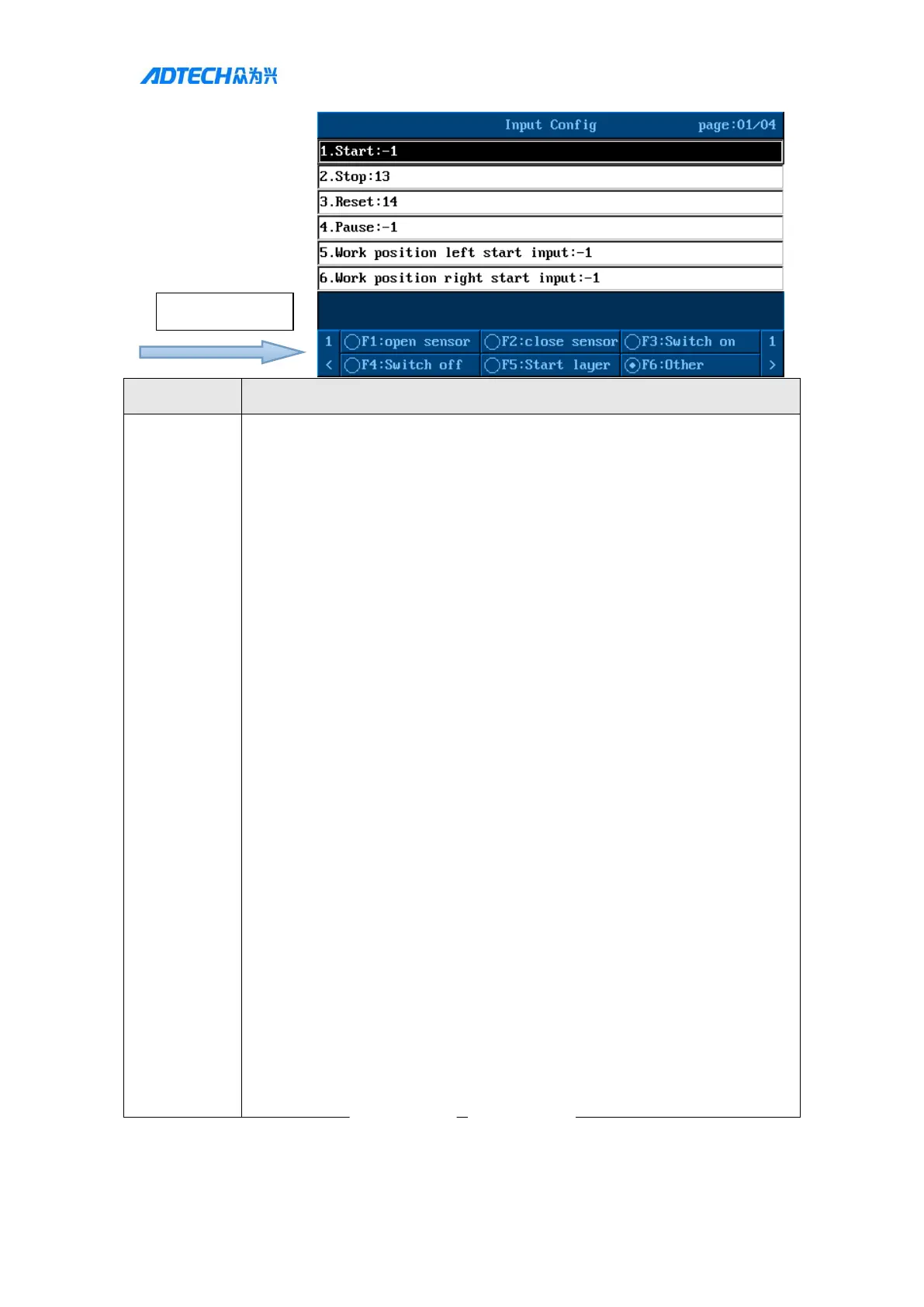
※Note: You can set the port number corresponding to the common input
function. Setting to -1 will disable this function.
1) Start: External start button port (valid for single position system)
2) Stop: External emergency stop button port
3) Reset: External reset button port
4) Pause: External pause button port
5) Left position start: External left position start button configured when it is a
dual position system
6) Right position start: External right position start button configured when it is
a dual position system
7) Safe gate: Safety light gridRight
8) Left table safe gate: Left safety light grid
9) Right table safe gete: Right safety light grid
10) Safe gate electrical lever: Safety grating active level
11) Step key:Single step button input
12) External alarm input: When the signal level is low, the machining stops and
generatesalarm output
13) External needle aligning button: When the button is pressed for the first
time, XY moves to the aligning position, and when it is pressed again within 3
seconds, the Z axis moves to the aligning position
14) Back to standby position button: When the button is pressed, it moves to the
set standby position
15) Cycle machining switch button: When the button is pressed, it enters the
cycle machining state, and when it is lifted, it enters a single machining state
16) External glue gun control button: Manual glue open/close control
17) BCD DIP switch input start point: You can use two-digit BCD8421 DIP
switches to select files. The two-digitDIP switch occupies8 continuously input
points. For example, if the input start point is set to 17, the wiring method is
as follows: