Page 16 of 42
2.3.4.5.2 Sounder Circuit Lengths
The voltage drop on each alarm circuit should be calculated to ensure that the minimum voltage
at the end of the circuit exceeds the minimum required by each sounding device at the minimum
alarm circuit output voltage.
The voltage at the end of the circuit is given by:
Minimum Alarm Voltage = V
OUT(MIN)
– (I
ALARM
x R
CABLE
)
Minimum Output Voltage (V
OUT(MIN)
) is V
BAT(MIN)
– 1.0V = 20.0V
Alarm Current (I
ALARM
) is the sum of the loads presented by the sounding devices in
alarm.
Cable Resistance (R
CABLE
) is the sum of the cable resistance in both cores x cable length.
Cable Resistance (R
CABLE
) for 1.0mm
2
is 0.036 / metre
Cable Resistance (R
CABLE
) for 1.5mm
2
is 0.024 / metre
Cable Resistance (R
CABLE
) for 2.5mm
2
is 0.015 / metre
Insulation Resistance
(Core-Core and Core-
Screen)
]2M
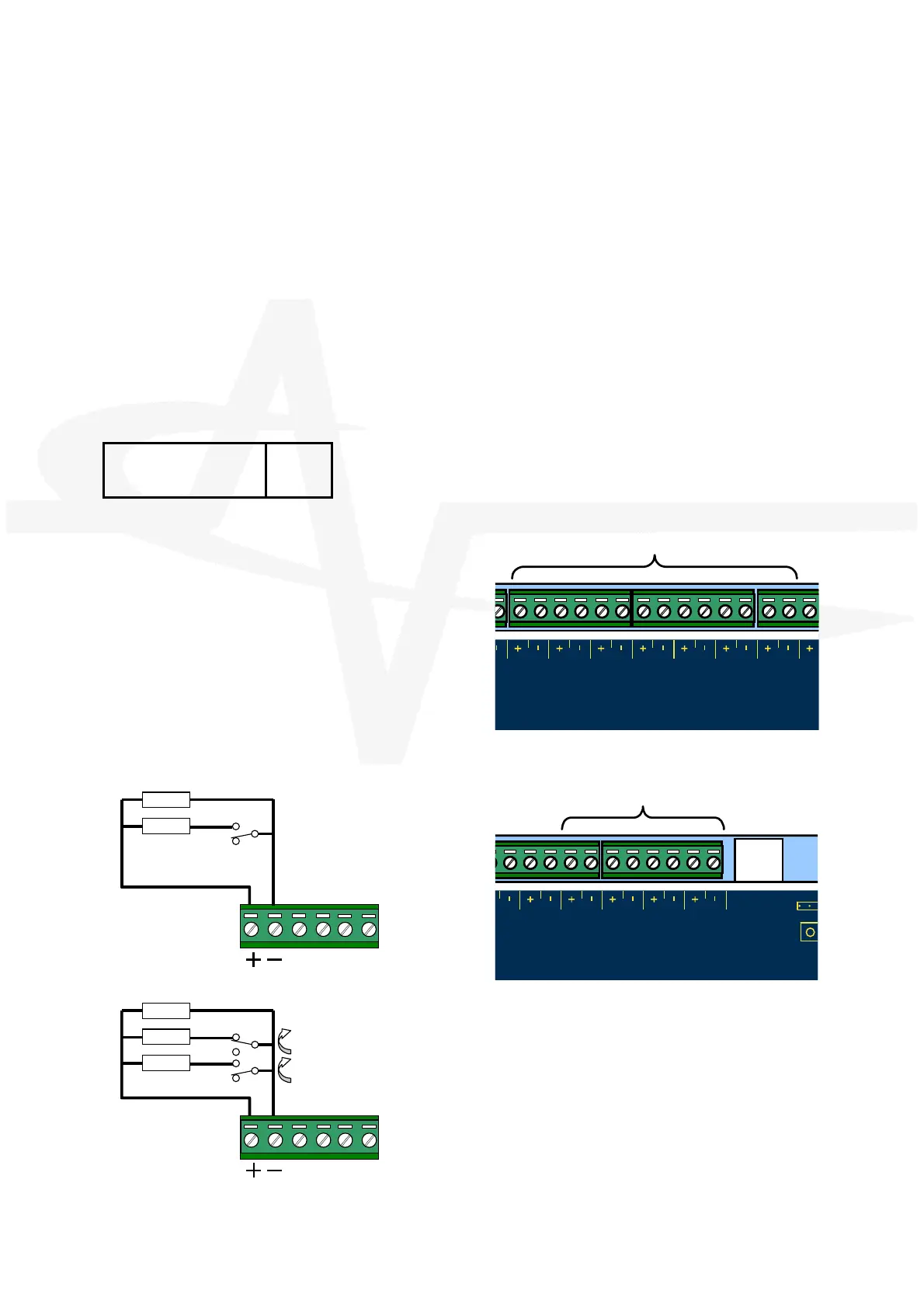
2.3.4.6 Input Circuits
Seven Fixed function Input circuits are provided for
the following functions:
MODE SELECT [Auto / Manual], MANUAL
TRIGGER, HOLD, ABORT, PRESSURE MONITOR,
VALVE MONITOR and FLOW MONITOR.
Four Programmable Function Input Circuits are
provided.
Each input circuit is monitored for open and short
circuit conditions – see typical arrangement below.
EOL = 6800. Maximum line impedance 50.
Connect to volt-free switches / relay contacts only.
R
MOD E
Select
Manual
Trig ge r
HO LD
BO
R
T
P
r
e
s
s
u
r
e
M
o
n
i
t
o
r
V
L
V
E
M
o
n
i
t
o
r
FL OW
Mo nitor
ct
Ou
6K8
470R
TYPICAL SWITCH
RRANGEMENT
U
S
B
RUN
uP MO
OW
nitor
ctuator
Output
PROG
Input-1
PROG
Input-2
P
R
O
G
In
p
u
t
-
3
P
R
O
G
I
n
p
u
t
-
4
6K8
6K8
470R
VALVE FULLY OPEN
VALVE FULLY CLOSED
VALVE MONITOR SWITCH
RRANGEMENT
The VALVE MONITOR input is used to monitor
the open / closed state of a mechanical valve
control device.
If the valve is in an indeterminate state (neither
fully open nor fully closed) for more than 30
seconds, the panel will indicate a fault
condition.
If unused, connect a 3300 (or 2x 6800 in
parallel) EOL across the terminals.