Page 9 of 42
2 Installation
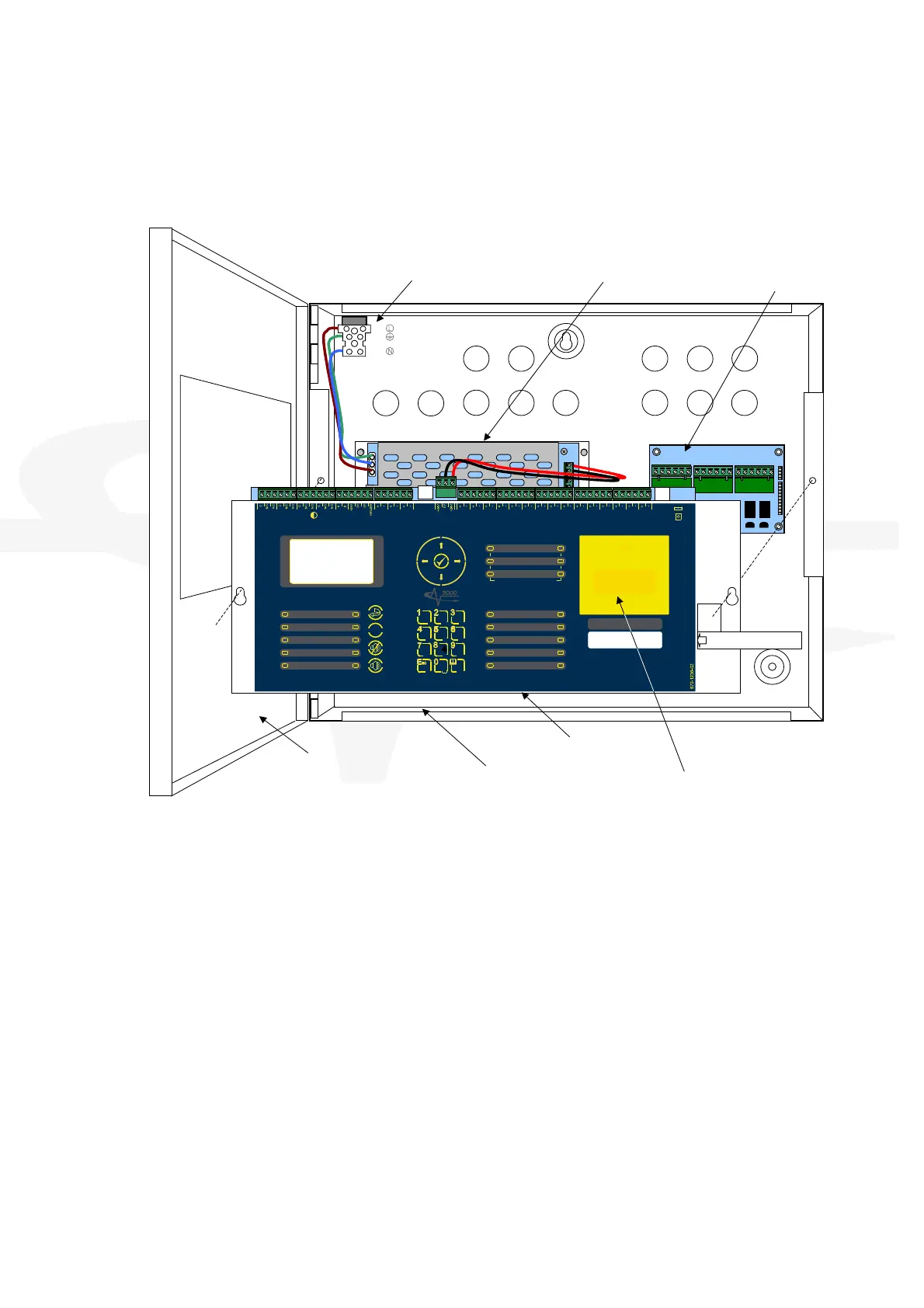
2.1 Identification of Parts
The following diagram shows the major parts of the panel.
LIVE
EARTH
NEUTR AL
U S B
SUPPLY
PSU
Comms
P
R
O
G
R
U
N
u
P
M
O
D
E
R
E
B
O
O
T
R
e
l
a
y
-
1
F
I
R
E
R e l a y
Re la
y
-
2
F A U L T
R e l a y
R S 4 8 5 A U X
S u p p l y
Z O N E
-
1 -
ZO NE
- 2 -
ZO NE
- 3 -
SN DR
- 1 -
SN DR
- 2 -
SN DR
- 3 -
MO DE
Se lect
Ma nua l
Trig ger
HO LD A BOR T Pres sure
Monit or
VALV E
Mo nitor
FL OW
Mo nitor
Ac tuat or
Ou tput
PROG
Input-1
PROG
Input-2
PROG
Input-3
PROG
Input-4
MANUAL ONL
AUTO +
MANUAL
LOW PRESSURE
MANUAL
DISABLED
DISABLED
FAULT
TIMER HELD
ABORTED
RELEASE
IMMINENT
RELEASED
EXTIN GUISH ANT
P
O
W
E
R
S
S
T
E
M
F
A
U
L
T
T
E
S
T
S
O
U
N
D
E
R
D
E
L
A
E
D
D
I
S
A
B
L
E
S
O
U
N
D
E
R
D
I
S
A
B
L
E
D
F
A
U
L
T
S
O
U
N
D
E
R
F
A
U
L
T
F
I
R
E
S
I
L
E
N
C
E
D
G
E
N
E
R
A
L
- 1 -
DETECTION ZON ES
FI RE FA ULT/
TE S T /
DI SA BLE
- 2 -
- 3 -
ESC MENU
WX
ZTUVPQRS
GHI JKL MNO
DEFABC
R ES ET
SIL ENCE/
RE SOU ND
M UTE
!
SOU ND
ALARM S
(HOLD 2s)
BS EN 54-2: 1998 BS EN54-4: 19
9
8
BS EN 12094-1: 2003 CLASS-
A
EXTINGU ISHANT
RELEASE
PULLDOWN ANDPRESS BUTTON
DOOR
BACK BOX
CHASSIS
SSEMBLY
C INPUT
PSU MODULE
MANUAL RELEASE
COVER
RELAY MODULE
(OPTIONAL)
SLIDE-IN LABEL
The panel comprises a back box, door, chassis assembly and PSU module.
The chassis is mounted onto the back box via two screws and keyhole mounting holes. The
screws do not have to be removed to remove the chassis.
The chassis contains the main printed circuit card with terminal block connections for field wiring.
A fascia label is affixed to the front of the chassis providing the user controls and indications (LCD
and LED indicators). A hinged yellow plastic cover is fitted to the front face and provides access
to the manual release button.
The PSU module converts the in-coming AC Supply to 24V DC (nominal) and provides battery
charging. The PSU is connected to the chassis via a DC Cable and a serial communications
cable. The PSU design is to BS EN54-4: 1998 +A2 and provides monitoring for AC failure, battery
missing, battery low, charger failure and battery internal resistance.
Standoff pillars are provided in the back box to fit a standard Mxp-008 8-Way Relay Module. This
is connected to the main printed circuit card via ribbon cable.
Up to two (programmable function) key-switch assemblies can be fitted to the chassis plate below
the manual release cover. The cables plug onto the main printed circuit card. Slide-in labels with
pre-printed text are available.