Page 21 of 42
3 Programming
3.1 Introduction
These instructions cover the configuration and programming of the panels.
NOTE: The panel is delivered in a non-configured condition. In this mode (or if the panel is
returned to factory default settings) the panel defaults to MANUAL ONLY mode of operation.
After configuring the panel, use the Level 2 EXTINGUISH MODES menu option (or the
configured key-switch / inputs) to set the panel into the AUTO+MANUAL mode.
3.1.1 Access Levels
The panel operation is protected from inadvertent and erroneous misuse by means of four access
levels. These levels are as follows:
Level 1 Untrained user
Level 2 Authorised User
Level 3 Commissioning, Service and Maintenance
Level 4 Commissioning, Service and Maintenance – Special Tools Required
This document covers the Level 3 functions. For details on the operation and use of the panel at
Levels 1 & 2, refer to User Manual 680-148. Full details are supplied with any special tools.
A level-3 password is required to enter the commissioning menus. For details of Passwords, refer
to Section 3.3.6.
Level-3 Passwords.
If this number is lost, it is not possible to enter commission mode functions.
Refer to 5.1 for further information.
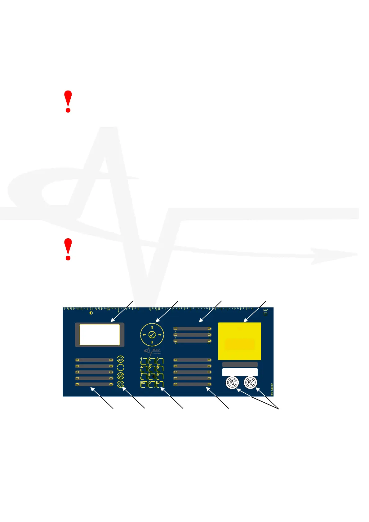
3.1.2 Front Panel Controls and Indications
USB
S UPPLY
P
S U
C o m m s
P R O G R U N
u P M O D E
R E B O O T
R e l a y - 1
F
I
R
E
R e l a y
R e l a y - 2
F A U L T
R
e
l
a
y
R S 4 8 5 AU X
Sup pl
y
Z O N E
-
1
-
Z O N E
-
2
-
Z O N E
-
3
-
SN DR
- 1 -
SND R
- 2 -
SN DR
- 3 -
MO DE
Selec t
Ma n ual
Trig ger
HOL D AB OR T Pr essu re
Mon itor
VALVE
Mo nitor
FL OW
Mo nito r
Ac tu ato r
O utp ut
PROG
Input-1
PROG
Input-2
PROG
Input-3
PROG
Input-4
MANUAL ONL
AUTO +
MANUAL
LOW PRESSURE
MANUAL
DISABLED
DISABLED
FAULT
TIMER HELD
ABORTED
RELEASE
IMMINENT
RELEASED
EXTINGUISHANT
P
O
W
E
R
S
S
T
E
M
F
A
U
L
T
T
E
S
T
S
O
U
N
D
E
R
D
E
L
A
E
D
D
I
S
A
B
L
E
S
O
U
N
D
E
R
D
I
S
A
B
L
E
D
F
A
U
L
T
S
O
U
N
D
E
R
F
A
U
L
T
F
I
R
E
S
I
L
E
N
C
E
D
G
E
N
E
R
A
L
- 1 -
DETECTION ZONES
FIR E FA U LT /
TES T /
DIS ABLE
- 2 -
- 3 -
E
S
C
MENU
WXYZTUVP
Q R S
G H I JKL MNO
DEFABC
R
E
S
E
T
S
I
L
E
N
C
E
/
R E S O U N D
M
U
T
E
!
S
O
U
N
D
A
L
A
R
M
S
( H O L D 2 s )
BS EN 54-2: 1998 BS EN 54-4: 1998
BS EN 12094-1: 2003 CLASS-A
EXTINGUISH ANT
RELE ASE
PULL DOWN AND PRESS BUTTON
Key-Switch Assembly Extinguishant Status Number Buttons Control Buttons General Fire Status
LCD
Navigation Buttons Detection Zone Status
Manual Release Button
The LCD along with the LED Indicators shows the operating status of the system. Examples of
the information presented is shown below: