8 Meadowbank Road, Carrickfergus, BT38 8YF, Northern Ireland www.advancedsensors.co.uk
Page 12 of 93
OIW-HBO-0002-EX-005
OIW EX SERIES-SIDE STREAM
OPERATION MANUAL
Rev. 004 MAY 2015
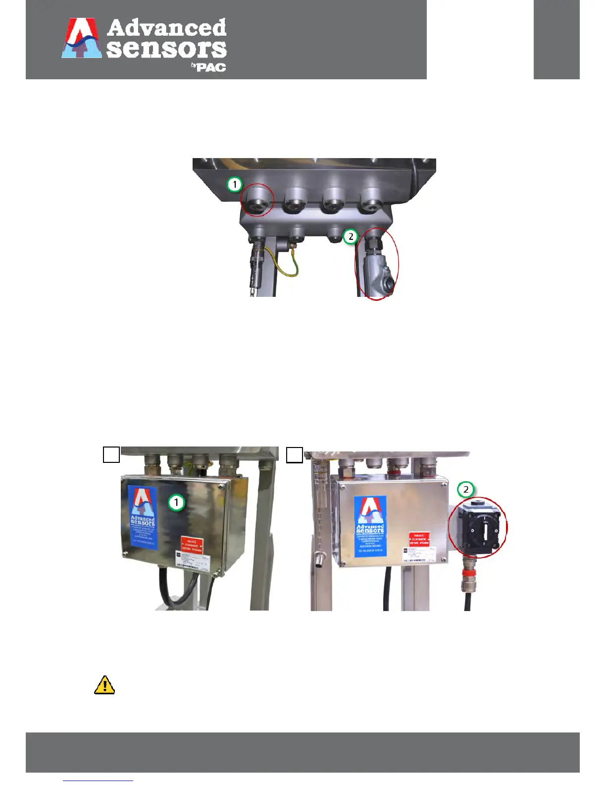
Terminal box not fitted
When a terminal box is not required, such as Class 1 division 1 installations, the front left entry (#1 in Figure 4) is used for
connecting the mains power and the entry to the back right side of the enclosure (#2 in Figure 4) is used to connect the
valve conduit.
Figure 4: Enclosure without a terminal box. 1. Mains entry 2. Valve conduit entry
Terminal box fitted (including with an isolation switch)
Terminal boxes are mounted below the enclosure door and use the 2 outermost M25 entries as shown in Figure 5. The
remaining 2 innermost M25 entries are inaccessible and therefore fitted with nickel plated brass stopping plugs.
Terminal boxes are equipped with 4 x M20 general purpose entries (on the underside); 1 for valve conduit entry (#4) and
the remaining 3 are free for other requirements; such as drain plugs, Ethernet, 4-20 mA and/or Alarm contact cables to
be wired into the control room. Unused entries are fitted with M20 stopping plugs. Finally 1 x M25 entry is allocated to
mains power entry (#2).
Figure 5: Enclosure fitted with 1. a terminal box and 2. An isolation switch
Isolation switches are fitted to the side of the terminal box, as shown above in Figure 5: Enclosure fitted with 1. a
terminal box and 2. An isolation switch #2.
INFORMATION: For electrical connection information please consult the Side Stream Installation manual,
OIW-HBO-0001-EX-0014.
a
.
b.
 Loading...