11 AIMB-503 User Manual
Chapter 1 General Information
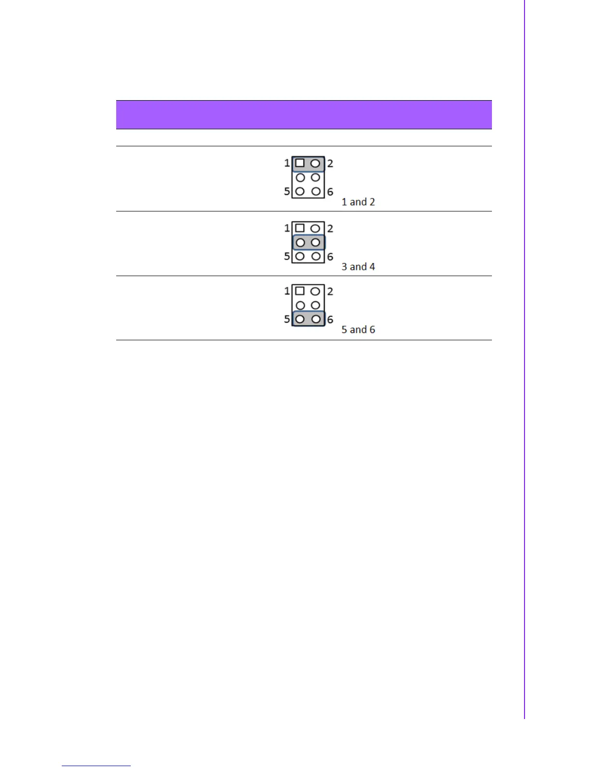
1.8.7 JSETCOM1_V1, JSETCOM2_V1: Power setting for COM1 &
COM2
1.8.8 JCASE1: Case Open Sensor
The AIMB-503 motherboard contains a jumper that provides a chassis open sensor.
The buzzer on the motherboard beeps when the case is opened.
1.9 System Memory
AIMB-503 has two 240-pin memory sockets for 1333/1600 MHz memory modules
with maximum capacity of 16GB (Maximum 8GB for each DIMM). AIMB-503 sup-
ports only non-ECC DDR3 memory modules.
1.10 Memory Installation Procedures
To install DIMMs, first make sure the two handles of the DIMM socket are in the
“open” position, i.e., the handles lean outward. Slowly slide the DIMM module along
the plastic guides on both ends of the socket. Then firmly but gently (avoid pushing
down too hard) press the DIMM module well down into the socket, until you hear a
click when the two handles have automatically locked the memory module into the
correct position of the DIMM socket. To remove the memory module, just push both
handles outward, and the memory module will be ejected by the mechanism.
1.11 Processor Installation
The AIMB-503 is designed for LGA1150, Intel Core i7/Core i5/Core i3 processor.
Table 1.9: JSETCOM1_V1, JSETCOM2_V1: Power setting for COM1 &
COM2
Function Jumper Setting
Jumper position for RI# (Default)
Jumper position for 5V
Jumper position for 12V