Figure 2.4 M.2 SSD Installation
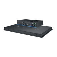
5. Attach the TPC computing box module to the FPM display module via the
board-to-board connector. Use the five screws of 1930000881 to secure
the computing box with the display module.
Figure 2.5 Attaching the TPC to the FPM Display
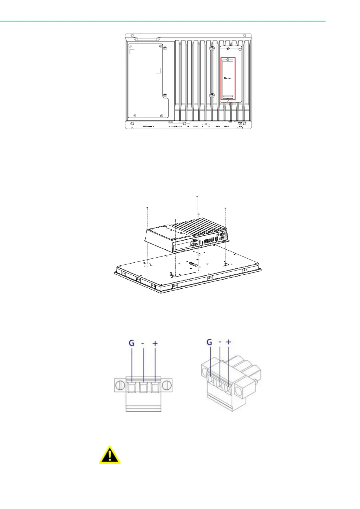
6. Connect the power connector to the 24 VDC power lines of a power
adapter or in-house power source.
Figure 2.6 Power Connector and Pin Assignment
The system may get damaged when the power is turned on
and the power source is not connected to the correct pins.
Le système peut être endommagé lorsque l'alimentation est
allumée et que la source d'alimentation n'est pas connectée
aux broches appropriées.