24
3.6.1 Lead Resistance Compensation
Warning: Before the compensation is executed, the MAX/MIN and HOLD modes
must be disabled.
To perform automatic compensation of the test lead resistance, proceed as
follows:
1. Short-circuit the leads connected to the meter.
2. Hold the button down until the display unit indicates the lowest
value. The device measures the resistance of the leads.
3. Release the button. The correction and the symbol are
displayed. The value displayed is stored.
NOTE: The correction value is stored only if it is ≤ 2Ω.
Above 2Ω, the value displayed blinks and is not stored.
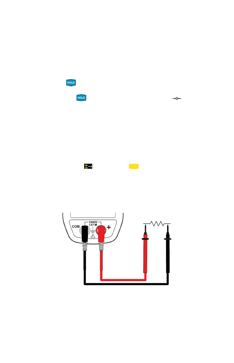
3.7 RESISTANCE MEASUREMENT
Warning: Before making a resistance measurement, make sure that the circuit is
off and all capacitors have been discharged.
1. Set the switch to and press the (yellow) button. The
symbol
is displayed.
2. Connect the black lead to the COM terminal and the red lead to the "+"
terminal.
3. Connect the test probes or the alligator clips to the circuit or component
to be measured.
The measured value is displayed on the screen.
NOTE: To measure low resistance values, first perform lead resistance
compensation (see § 3.6.1).