29
3.11.2 Balanced 3-Phase Power Measurement
1. Set the switch to and select VA, var, or PF by pressing the
button until the desired choice is reached
2. Press the (yellow) button until the symbol is displayed.
3. The device automatically displays AC+DC. To select AC, DC, or
AC+DC, press the (yellow) button until the desired choice is
reached.
4. Connect the black lead to the COM terminal and the red lead to the "+"
terminal.
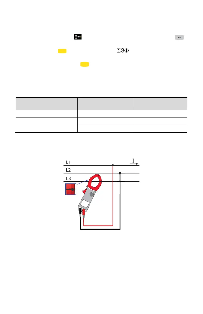
5. Connect the leads and the clamp to the circuit as follows:
If the red lead is
connected…
…and the black lead is
connected
…then the clamp is on the
conductor
NOTE: The arrow on the jaws of the clamp (see the diagram below) must point in
the presumed direction of flow of the current from the source to the load.
The measurement is displayed on screen.
NOTE: 3-phase power on a balanced 4-wire network can also be measured by
proceeding in the same way, or by proceeding as for the measurement on a
single-phase network, then multiplying the value by three.