40
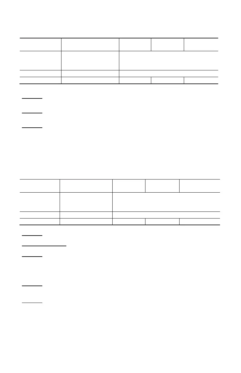
4.2.11 Active DC Power Measurements
(2)
(1)
Measurement
1 to 100% of the
measurement range
0 to 100% of the
measurement range
Note (1) - Display of O.L or ± O.L
- Above ±1800kW in REL mode.
Note (2) Any applied voltage greater than 1000V causes the emission of an
intermittent alarm beep to report a dangerous overload.
Note (3) The measurement result may be affected by an instability linked to the
current measurement (approximately 0.1A).
Example: For a power measurement made at 10A, the instability of the
measurement will be 0.1A/10A or 1%.
4.2.12 Active AC Power Measurements
(2) (4)
600kW
(1)
Measurement
measurement
0 to 100%
of the measurement range
Note (1) Bandwidth in AC in voltage = 3kHz, in current = 3kHz
Notes (2) and (3) of the previous § apply.
Note (4) Any power measured less than 5W is regarded as zero and causes the
display of dashes "----"
If the voltage is less than 0.15V or if the current is less than 0.15A, the
power measured is regarded as zero and causes the display of "----"
Note (5) The active powers are positive for power consumed and negative for
power generated.
Note (6) The signs of the active and reactive powers and power factor are
defined by the four-quadrant rule below:
The diagram below sums up the signs of the power as a function of the
phase angle between V and I:
Quadrant 1: Active power P sign + (power consumed)
Quadrant 2: Active power P sign - (power generated)
Quadrant 3: Active power P sign - (power generated)
Quadrant 4: Active power P sign + (power consumed)