42
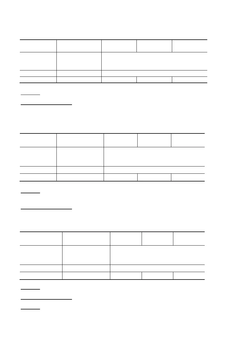
4.2.14 Measurement of Apparent AC Power
(2) (4)
600kVA
(1)
Measurement
measurement
0 to 100%
of the measurement range
Note (1) Bandwidth in AC in voltage = 3kHz, in current = 3kHz
Notes (2), (3) and (4) of the previous § apply.
4.2.15 Measurement of Apparent AC+DC Power
(2) (4)
(1)
Measurement
measurement
0 to 100%
of the measurement range
Note (1) - Display of OL above 900kVA in single-phase (1000V x 900A)
- Bandwidth in AC in voltage = 3kHz, in current = 3kHz
Notes (2), (3) and (4) of the previous § apply
4.2.16 Measurement of Reactive AC Power
(2) (4)
600 kvar
(1)
Measurement
measurement
0 to 100%
of the measurement range
Note (1) Bandwidth in AC in voltage = 3kHz, in current = 3kHz
Notes (2), (3) and (4) of the previous § apply
Note (5) In single-phase, the sign of the reactive power is determined by the
phase lead or lag between the V and I signs, while in balanced three-
phase, it is determined by the calculation on the samples.