13
8.5. ELECTRIC CONNECTIONS
All the electrical opera-
tions must be carried
out by STAFF IN POS-
SESSION OF THE NE-
CESSARY QUALIFICA-
TIONS BY LAW suitably
trained and informed
on the risks related to
these operations.
The characteristics of the
electrical lines and of the
related components must
be determined by STAFF
QUALIFIED TO DESIGN
ELECTRICAL SYSTEMS,
in compliance with the in-
ternational and national
regulations of the place of
installation of the unit and
in compliance with the re-
gulations in force at the
moment of installation
For the installation re-
fer only to the wiring
diagram supplied with
the appliance. The
electrical diagram
along with the manuals
must be kept in good
condition and ALWAYS
AVAILABLE FOR ANY
FUTURE SERVICING
ON THE UNIT.
It is mandatory to veri-
fy that the machine is
watertight before ma-
king the electrical con-
nections and it must
only be powered up
after the hydraulic and
electrical works have
been completed.
The DMP is completely wired and only
requires connection to the electric po-
wer supply network. Please verify that
the electrical mains features are suita-
ble for the absorption values indicated
in the electrical data table, also taking
into consideration any other machines
operating at the same time.
− The electric power supply must
respect the limits stated: if this is
not the case, the warranty will im-
mediately become null and void. Al-
ways check that the electric power
supply is disconnected before star-
ting any operation.
− The unit can only be activated cor-
rectly if the remote dehumidifica-
tion and ventilation remote consent
have been connected (connections
to the remote control panel sup-
plied). Regarding this, scrupulously
follow that stated in the wiring dia-
gram.
8.6. START-UP
Before start-up, check the electric
connection and the correct fixing of all
clamps.
• The power supply voltage must be
that stated on the unit plate
• Check that there are no gas leaks.
• Check that all hydraulic connections
have been installed correctly and that
the indications on the plate have been
respected.
• Before switch-on, check that all clo-
sure panels are in their position with
relevant screw fasteners.
If the unit does not start:
Check that the remote consent con-
tacts are enabled.
WARNING: Do not modify the unit elec-
tric connections or the warranty will
become immediately null and void.
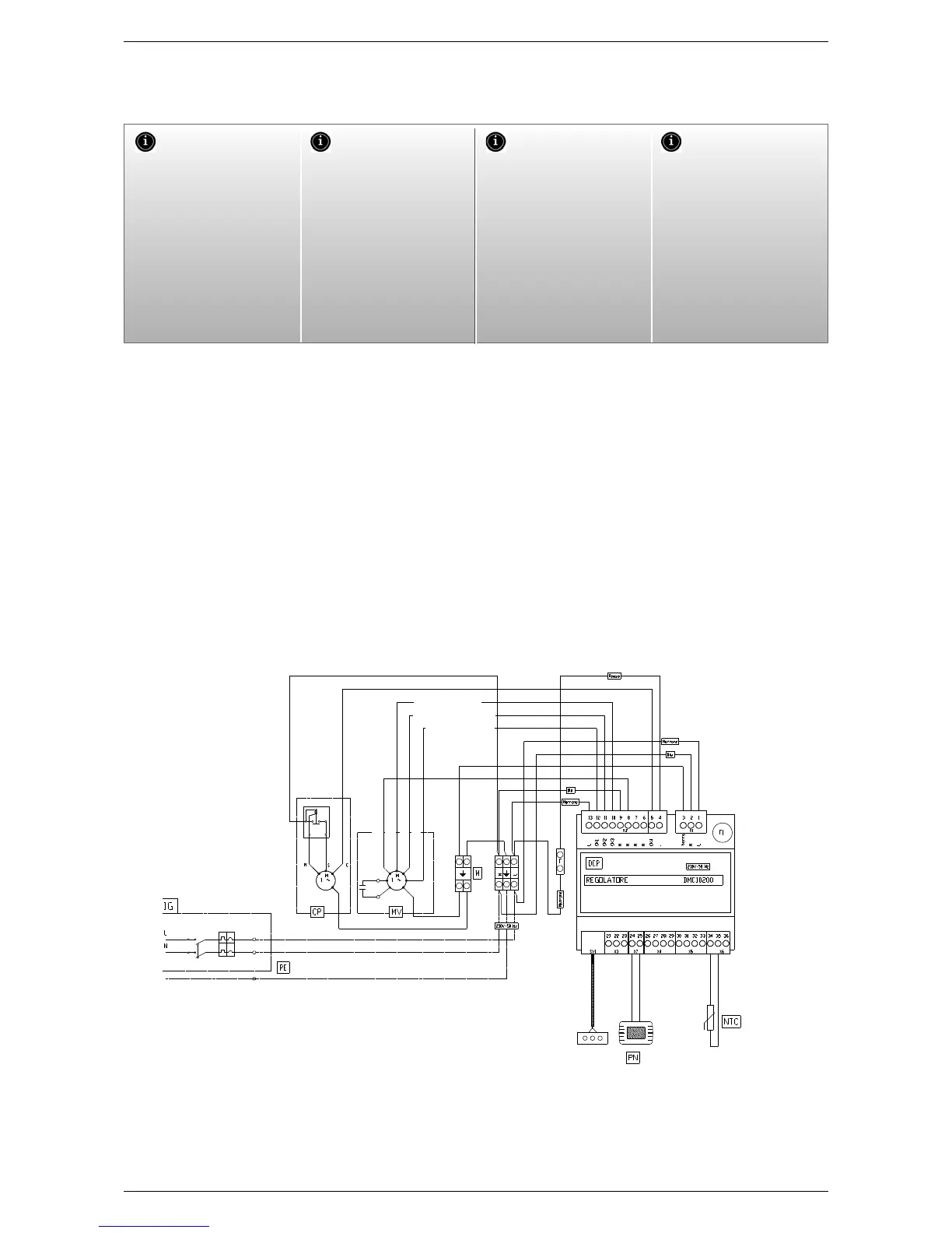
8.6.1. ELECTRIC CONNECTIONS
CP compressor
DCP adjuster circuit board
F1 fuse isolator switch
IG Master switch
L Phase
M Terminal board
MV Fan
N Neutral
PE Earth connection
B3 NTC water probe
PN Multi-function wall panel
Fan single-phase motor
1 = blue =common
2 = black =high
3 = brown = average
4 = red = low
5 = --------
6 = y/green
Signal
LED
Cable
Flat
blue
black
brown
red
black MAX speed
brown AVERAGE speed
RED MINIMUM
Speed
PROTECTION NOT SUPPLIED