17
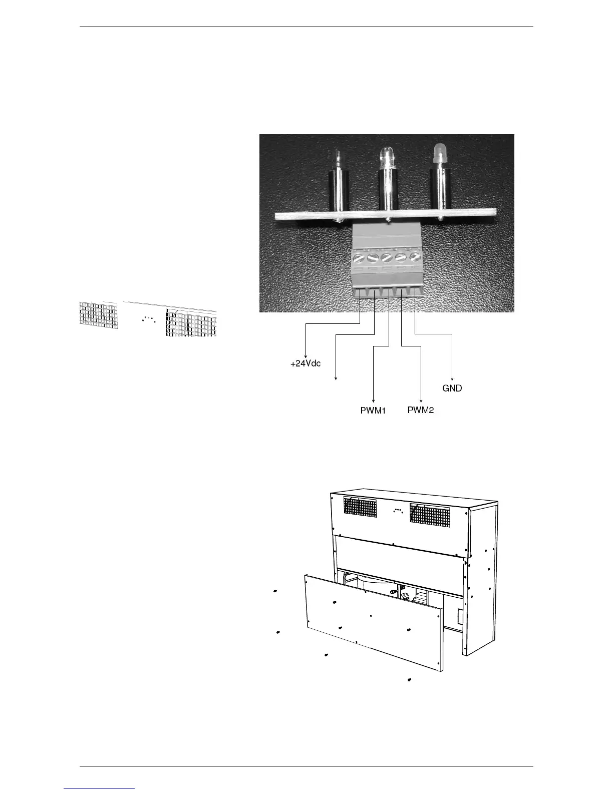
8.16. LED PANEL
The LED panel must be connected to
the low voltage control terminal board
(green connectors) at the clamps indi-
cated in the following layout:
8.17. DEHUMIDIFIER LED INTERFA-
CE CONNECTION LAYOUT
The green LED indicates the board po-
wer supply.
The blue LED indicates compressor
activation. If it flashes it indicates the
defrost cycle is in progress.
The red LED indicates the presence of
an alarm signal. In this case the LCD
terminal display which specific signal is
present.
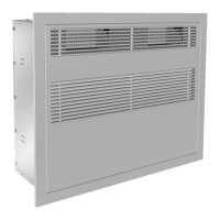
8.18. FRONT PANEL INSERTION
When the dehumidifier has been inser-
ted and the electric and hydraulic con-
nections and the connection to the wall
remote control panel have been made,
insert the front panel in the surroun-
ding frame.
8.19. REMOVAL OF THE FRONT
PANEL
Use two aluminium hooks to remove
the front panel. Place them between
the upper fins and centre in correspon-
dence with the vertical pipes. The panel
slides out by pulling upwards.
NOT
CONNECTED
DEHUMIDIFIER LED INTERFACE
CONNECTION LAYOUT