LOCAL OPERATION
3-63
AF test (audio frequency testing)
Overview
AF
COUNTER
TONES
GEN
AF
GEN
1
AF
GEN
2
AF
IN
AF
OUT
AF
OUT
AF
IN
DIST-
ORTION
METER
AF
VOLT-
METER
SERVICE
MONITOR
AMPLIFIER UNDER TEST
AF
FILTERS
C3380
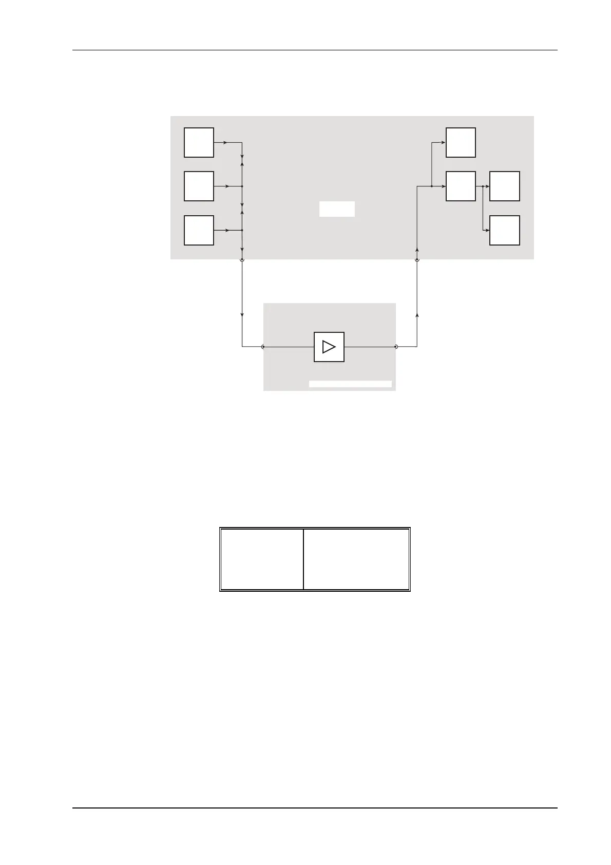
Fig. 3-16 Audio test setup
To enter the AF TEST mode press the blue [AF TEST] key. This will cause the screen and menu
shown in fold out diagram (6-0) to be displayed.
When the AF TEST mode is selected, the combined output from the AF generators, plus the data
generator facility, is available at the AF output connector. Signals fed to the AF input connector
are routed to the AF signal analyzing circuits. See Fig. 3-16, Audio test setup.
The frequency, level and shape parameters of the audio generators can be set within the following
limits:
Freq. range
5 Hz to 33 kHz
Level range
0.1 mV to 4 V rms
Shape option
Sine or square
By using the AF signal generators and the measuring functions of the Service Monitor, it can be
used for performance testing of passive and active AF circuits such as filters and amplifiers.
Frequency, level, distortion level, SINAD level and signal to noise ratio measurements can be
made. The oscilloscope facility is available to observe and measure waveforms. The tones
receiver facility is available for the performance checking of features such as digitally coded
squelch generators.
The AF output signal and the measuring facilities can each be used independently.


 To Next Page