ACCEPTANCE TESTING
5-7
RF output level
Specification
Level range:
−127 dBm to −21 dBm (N-type socket)
Accuracy:
± 2 dB up to 1 GHz
Test equipment
Description Minimum specification Example
RF power meter
± 0.1 dB from 10 MHz to 1 GHz
IFR 6960/A/B +
6920 sensor
Measuring
receiver
−21 dBm to −127 dBm, 2.5 MHz to 1 GHz
HP 8902A +
11772A sensor
Spectrum
analyzer
Noise floor < −127 dBm
IFR 2383
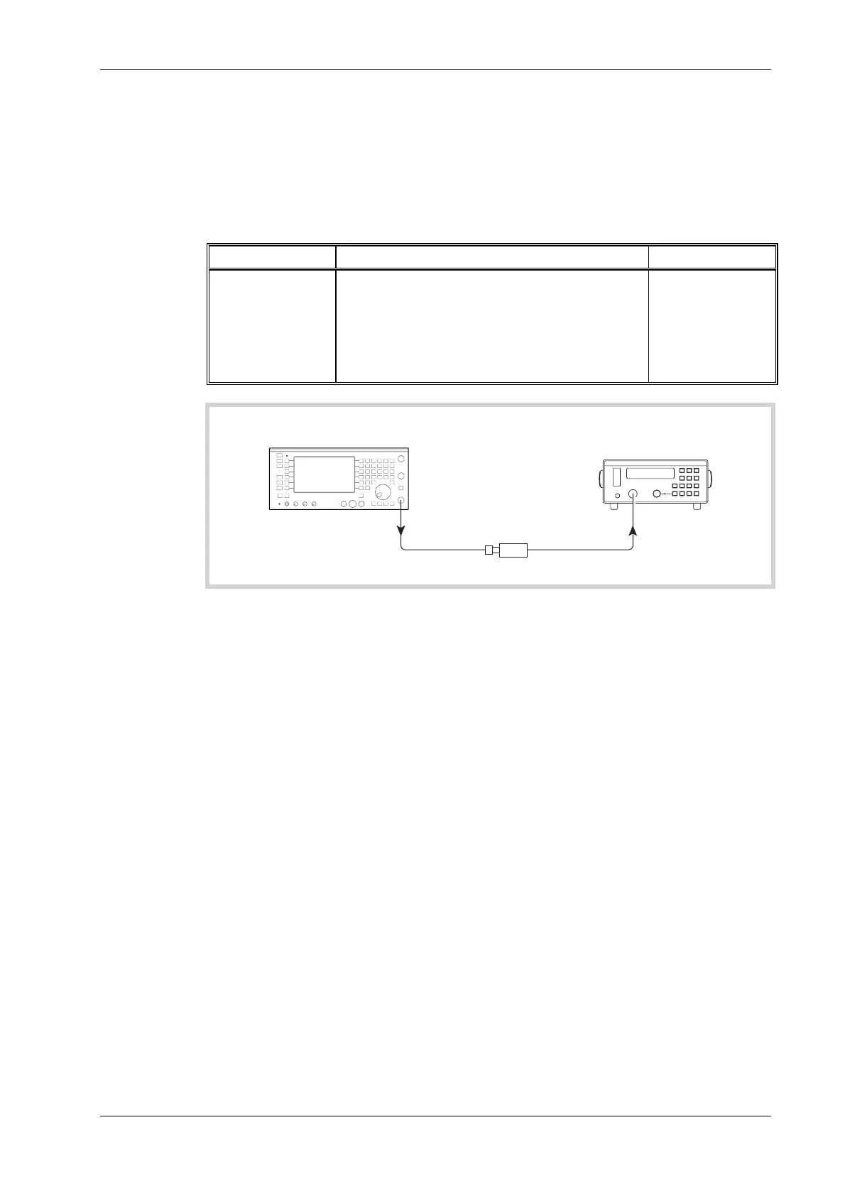
RF power meter
C6040
UUT
N TYPE
OUTPUT
SENSOR
INPUT
6920
Fig. 5-2 RF level set up
(1) Refer to Results table 5-2 on page 5-36. Connect the sensor to the UUT N-type output
socket, as shown in Fig. 5-2.
(2) Set the UUT to [Rx TEST], RF IN/OUT [SELECT] N-type output/antenna input mode,
[RF Gen], [ LEVEL] −21 dBm, [ FREQ] 10 MHz. All modulation and noise measurements
should be switched OFF.
(3) Check that the power meter indicates −21 dBm ± 2 dB.
(4) Select N-type output/N-type input mode and check that the level measured is
−21 dBm ±2 dB.
(5) Press RF IN/OUT [SELECT] until the mode returns to N-type output/antenna input.
(6) Repeat steps 3 to 5 for 100 MHz and then in 100 MHz steps up to and including 1000 MHz.


 To Next Page