INSTALLATION
2-9
Remote control connections
RS232
The serial port connection requires a 9 way female ‘D’ Type connector. This should be correctly
fitted to appropriate cable and the locking screws should be used to prevent undue strain from
being applied to the connector housing.
The pin connections are listed below and the pin locations shown in Fig. 2-3 RS232 serial port
connections (as seen facing panel).
Contact Function Contact Function
1 Not connected 6 DSR
2 Rx data in 7 RTS
3 Tx data out 8 CTS
4 DTR 9 Not connected
5 Ground
5
9
1
6
C0783
Fig. 2-3 RS232 serial port connections (as seen facing panel)
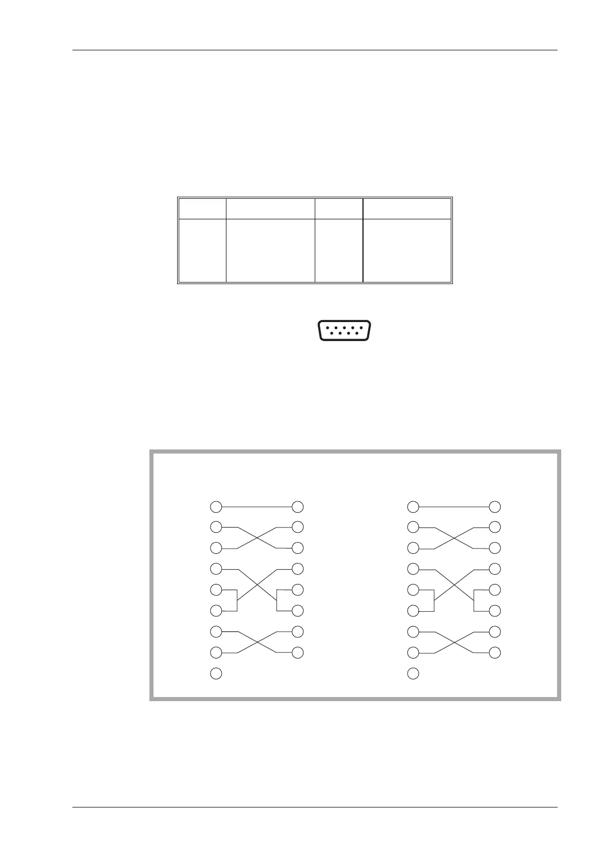
The use of a NULL MODEM cable assembly is required for connecting to control equipment such
as PCs.
The connections for 9 way to 9 way and 9 way to 25 way versions is shown in Fig. 2-4.
1
2
3
4
5
6
7
8
99
1
2
3
4
5
6
7
8
TXD
RXD
SG
CTS
DCD
DSR
RTS
TXD
RXD
SG
CTS
NOT
CONNECTED
NOT
CONNECTED
NOT
CONNECTED
NOT
CONNECTED
DSR
RTS
DTRDTR
9-WAY 9-WAY
SERVICE
MONITOR
SERVICE
MONITOR
PC
1
2
3
4
5
6
7
8
2
3
4
5
6
7
8
TXD
RXD
SG
CTS
DCD
DSR
RTS
TXD
RXD
SG
CTS
DSR
RTS
DTRDTR 20
9-WAY 25-WAY
PC
C3383
Fig. 2-4 Null modem connections


 To Next Page