ACCEPTANCE TESTING
5-13
Amplitude modulation
Specification
Carrier range:
400 kHz to 1.05 GHz
Resolution:
1%
Accuracy (up to 85% AM)
Carrier frequency 1.5 to
400 MHz.
±7% of setting ± 1 digit for modulation frequency 1 kHz.
±10% of setting ± 1 digit for modulation frequencies of 50 Hz to 5 kHz.
±15% of setting ±1 digit for modulation frequencies from 50 Hz to
15 kHz.
Distortion:
Less than 2% at 1 kHz for modulation depth 30% , CCITT weighted.
Test equipment
Description Minimum specification Example
Modulation meter RF I/P 500 kHz to 400 MHz AM Measurement
accuracy up to 85% depth:- ±1% of reading at
1 kHz mod rate. ±2.5% of reading for mod rates
from 50 Hz to 15 kHz
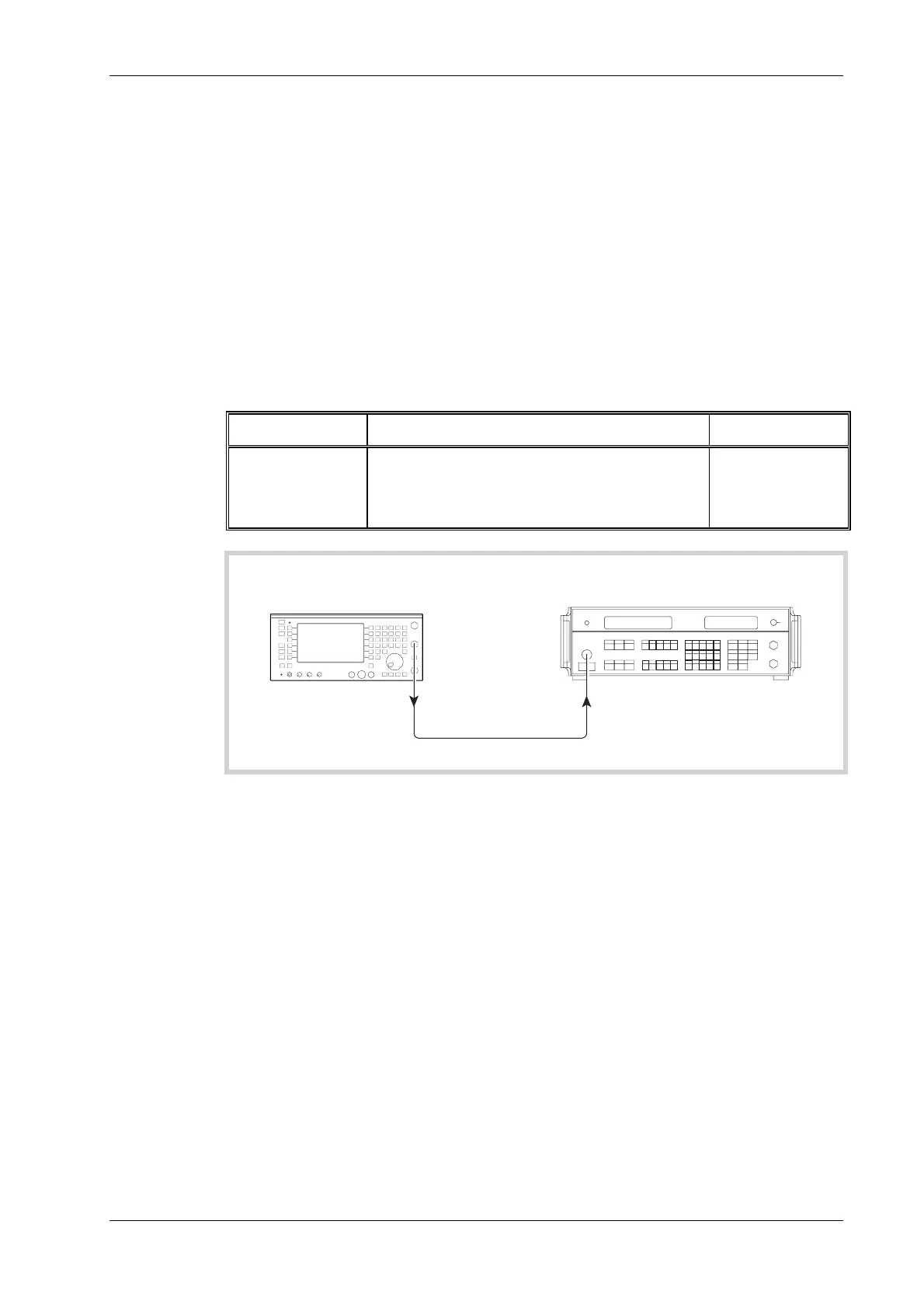
IFR 2305
UUT
C6046
RF INPUT
BNC
OUTPUT
Modulation meter
Fig. 5-8 Internal AM accuracy checks
(1) Refer to Results table 5-10 on page 5-40. Connect the test equipment as shown in Fig. 5-8
(BNC output socket on UUT).
(2) Set the UUT to [Rx TEST], RF IN/OUT [SELECT] BNC output, [RF Gen],
[LEVEL] 0 dBm, [FREQ] 1.5 MHz, [Mod Gen], [Gen 2], [FREQ] 1 kHz, [LEVEL] 50%.
(3) Set the Modulation meter to monitor AM in a 0.3 to 3.4 kHz bandwidth.
(4) Check the Modulation meter for a reading within ±7% of setting ± 1 digit.
(5) Repeat step 4, but with the UUT RF generator set to each of the remaining carrier
frequencies shown in the Results table 5-10 on page 5-40.
(6) Refer to Results table 5-11 on page 5-40. Set the UUT to [RF Gen], [FREQ] 100 MHz,
[LEVEL] 5 dBm, [∆ INC] 1 dB, [Mod Gen], [Gen 2], [LEVEL] 70% and check the
Modulation meter for a reading within ±7% of setting ±1 digit. Using the level decrement
arrow key, decrement the RF level by 1 dB and repeat check. Repeat in 1 dB decrements
down to −15 dBm.
(7) Refer to Results table 5-12 on page 5-41. Set the UUT to [RF Gen], [LEVEL] 0 dBm,
[Mod Gen], [Gen 2], [LEVEL] 5%.