GENERAL INFORMATION
1-3
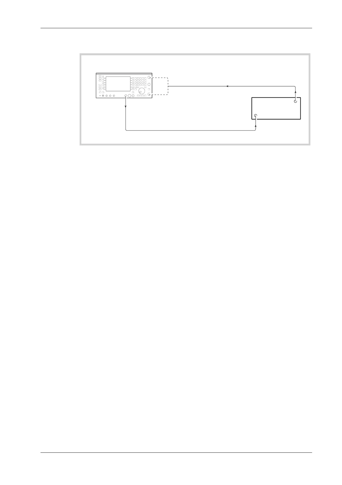
Transmitter testing
Service Monitor
Tx
Under
Test
AF GENERATOR
OUTPUT
AF (MODULATION)
INPUT
MODULATED RF SIGNAL
C6025
Fig. 1-1 Transmitter test setup
The transmitter test procedure uses:
The AF generators, to provide a source of modulation for the transmitter under test.
The RF power meter, to measure the mean output power level of the transmitter.
The RF counter, to obtain the mean RF frequency of the transmitter output.
The modulation meter, to measure the modulation depth or the deviation level and to
provide a demodulated output signal. Single sideband transmissions can be demodulated
when the SSB option is implemented.
The AF counter, to measure the frequency of the demodulated signal.
The distortion meter, to obtain the signal to noise level, the modulation distortion
percentage or the modulation SINAD level of the transmitter.
The oscilloscope, to view the demodulated signal and to measure the modulation levels.
The tones generator, to modulate transmitters of systems using tone calling.
The tones decoder, to demodulate tones generated by the transmitter.
The AF amplifier and loudspeaker, to monitor the demodulated signal.
The spectrum analyzer facility, which is a separate operating mode (SPEC ANA), can be used to
study the sidebands and any harmonics produced by the transmitter, either by direct connection or
by off-air monitoring.