ACCEPTANCE TESTING
5-8
ALC linearity
(1) Refer to Results table 5-3 on page 5-37. Connect the sensor to the N-type output socket, as
shown in Fig. 5-2.
(2) Set the UUT to [RF Gen], [LEVEL] −21 dBm, [∆ INC] 1 dB, [FREQ] 10 MHz.
(3) Increment the RF output of the UUT in 1 dB steps down to −38 dBm, ensuring that the
indication on the power meter is within ±2 dB of each level set.
(4) Return the UUT RF level to −21 dBm.
(5) Set the UUT carrier frequency to 500 MHz and repeat step 3. Refer to Results table 5-4 on
page 5-38.
(6) Set the UUT carrier frequency to 1 GHz, return the level to −21 dBm and repeat step 3. Refer
to Results table 5-5 on page 5-38.
BNC output mode
No claim is made on the output level accuracy of the BNC socket. The following is a functional
check to ensure correct internal operation.
(1) Connect the 6920 sensor to the BNC output, as shown in Fig. 5-2.
(2) Set the UUT to [Rx TEST], RF IN/OUT [SELECT] BNC output, [RF Gen],
[LEVEL] −21 dBm, [FREQ] 10 MHz. All modulation and noise measurements should be
switched OFF.
(3) Check that the power meter indicates −21 dBm ± 4 dB.
(4) Repeat step 3 for 100 MHz and then in 100 MHz steps up to and including 1000 MHz.
Attenuator accuracy
The following test will confirm that the attenuator performs to the published performance
specification. In the event of the receiver not being available, an alternative method to
functionally test the attenuator is also suggested.
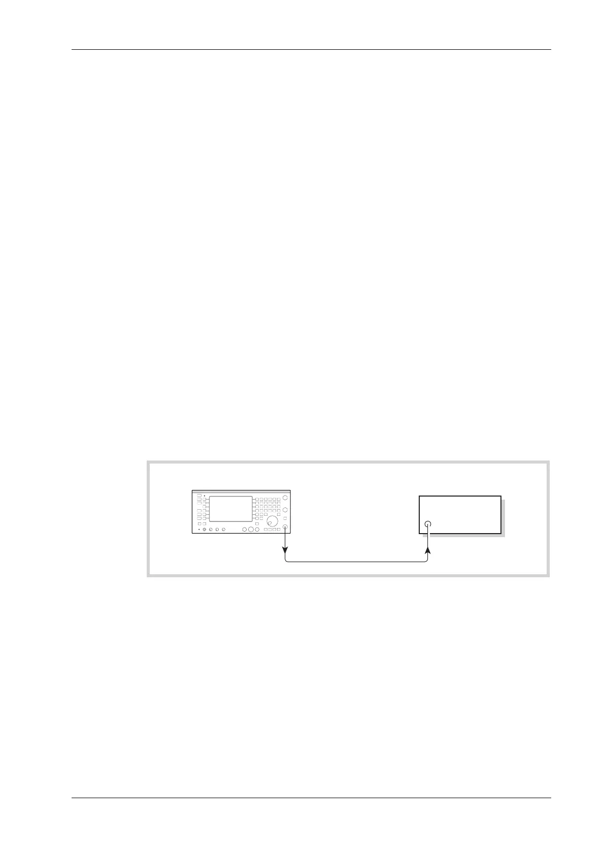
Measuring
receiver
C6041
UUT
N TYPE
OUTPUT
Fig. 5-3 Attenuator accuracy test set up
(1) Connect the test equipment as shown in Fig. 5-3.
(2) Set the UUT to [RF Gen], [ LEVEL], −21 dBm, [ FREQ] 2.5 MHz.
(3) Tune the receiver to the frequency set on the UUT RF Generator and measure the RF level.
(4) Decrement the output of the UUT in 10 dB steps down to an RF level of −121 dBm
measuring the RF level at each step.
(5) Repeat steps 2 to 4 for frequencies of 500 and 1000 MHz.