TECHNICAL DESCRIPTION
4-7
Tx test mode
When operating in the Tx TEST mode the Service Monitor has to provide a source of modulation
for the transmitter being tested and also analyze the RF output signal from the transmitter.
Modulation sources
The modulating signal is provided by one or both of the audio generators or the data generator and
is taken from the AF output connector on the front panel.
PROGRAMM-
ABLE
ARRAY
PROGRAMM-
ABLE
ARRAY
LOOK-UP
TABLES
EPROM
LOOK-UP
TABLES
EPROM
A.F. OUTPUT
DRIVER
MODULATION
DRIVER
LOOK AND LISTEN
SWEEP DRIVER
DATA
GENERATOR
(AF GEN. 2
ONLY)
AF GEN 2
WAVEFORM
SHAPE
DATA
TO A.F.
O/P ON
FRONT
PANEL
TO R.F.
GEN.
MOD.
CONTROL
TO 90 MHz
VOLTAGE
CON-
TROLLED
OSC.
AF GEN 1
WAVEFORM
SHAPE
DATA
AF GEN 2
OUTPUT
LEVEL
DATA
AF GEN 2
FREQ.
DATA
AF GEN 1
OUTPUT
LEVEL
DATA
AF GEN 1
FREQ.
DATA
D
A
D
A
D
A
D
A
A
A
A
B
B
B
C
C1412
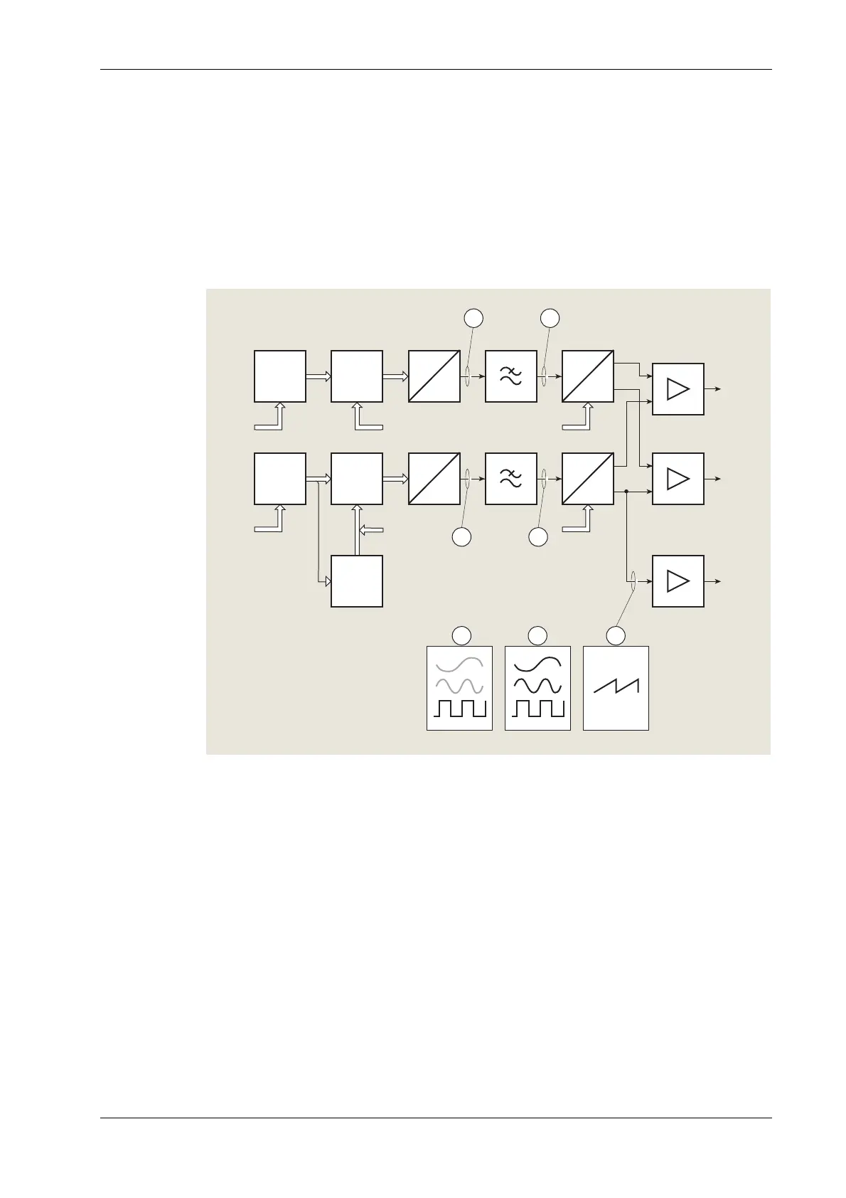
Fig. 4-3 AF generator detailed block diagram
Audio generators
Included in the monitor are two audio generators, shown as ‘AF generators’ on the simplified
block diagram. They are used as modulation sources for the Tx, Rx and Dx TEST modes and as
audio test signal generators in the AF TEST mode. Fig. 4-3 is a detailed block diagram of the AF
generators. They have a frequency range of 20 Hz to 20 kHz. The output waveform of either
generator can be switched between sine wave or square wave. Both generators are of similar
design, with minor variations. The generator designated ‘GEN 2’ is also used for other functions
which do not conflict with its functions as an audio generator. These uses will be mentioned
where relevant.