TECHNICAL DESCRIPTION
4-2
Overview
This simple description is provided to give the user an insight into the working of the Service
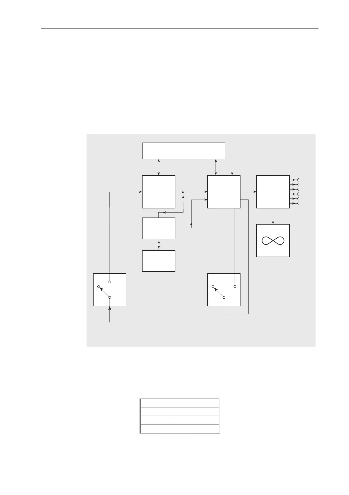
Monitor at the block diagram level. See Fig. 4-2 Simplified block diagram.
The power supply and display unit are described first. The functional circuit blocks of each test
mode are then described in sequence.
The Service Monitor is of modular construction, comprising a number of printed circuit boards, (at
least 15, depending on options included). These are housed in two sub-assemblies, along with
input and output attenuators, power supply, front panel, rear panel and display unit modules. The
Service Monitor is microprocessor controlled and software driven.
Power supply
C6038
AC-DC
CONVERTER
12 V Ni-mH
BATTERY
PACK
BATTERY
CHARGER
DC INPUT
11 to 32 V
ON/CHARGE
ON/OFF
AC INPUT
90 to 264 V
45 to 440 Hz
DC-DC
CONVERTER
DC OUTPUT
+24 V
24 V
+12 V
+5 V
12 V
0V
-
-
COOLING FAN
CONTROL BOARD
Fig. 4-1 Block diagram of power supply module
The power supply module is a switched mode design which will operate from an AC supply of 90
to 265 V, 45 Hz to 440 Hz or a DC supply of 11 to 32 V.
The circuits of the instrument require supplies of:
+5 V 3.0 A
+12 V 2.5 A
-12 V 1.2 A
36 V 100 mA output


 To Next Page