LOCAL OPERATION
3-8
Rear panel controls and connectors
T10AH250V
C6031
SERIAL
PORT
AC SUPPLY
100-240V ~
50-60Hz
108-118V ~
50-400Hz
190VA MAX
T2AL250V
EXT MOD
IN
EXT. STD
1/2/5/10MHz
DEMOD
OUT
100W MAX
+
-
11-32V
6
5324
8
7
910111
!
DC SUPPLY
CHARGE ON
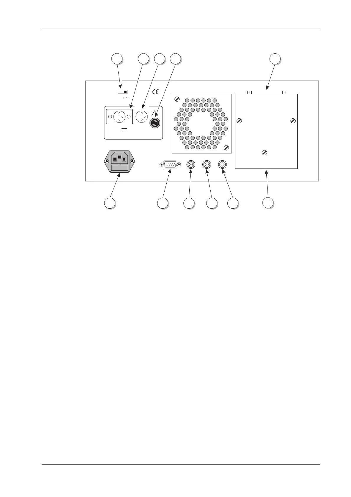
Fig. 3-3 Rear panel layout, (with optional GPIB fitted
On the rear panel of the instrument are:
(1) AC power supply input connector. One range for all mains voltages. See the Performance data
section in Chapter 1. The AC supply fuse is contained within this connector.
(2) Power switch. The power switch has two positions: ON or CHARGE. The ON position connects
the output of the Service Monitor’s power supply module to the instrument; the CHARGE position
allows the power supply to recharge the internal battery (if fitted). See Getting started; on Page
3-9.
(3) DC supply input voltage connector. For powering the instrument from DC supplies. See
Performance data, in Chapter 1.
(4) DC supply pin connection diagram. Shows the polarity of the DC power connector
(5) DC supply fuse.
(6) GPIB interface connector. This connector is only present when the GPIB interface option is
fitted. Connection details are given in Chapter 2, under Remote control connections, GPIB.
(7) GPIB interface unit. Optional. See (6) above.
(8) External frequency standard input. This can be 1, 2 5 or 10 MHz; the Service Monitor
identifies the applied frequency. In the event of external standard failure, control reverts to the
internal standard.
(9) Demodulated signal output. The demodulated signal removed from the input RF signal is
brought to this connector for feeding to external equipment.
(10) EXT MOD IN (External modulation input). A signal applied to this connector can be used as a
modulation source for the receiver test signal. The input level of the applied signal should be
1.00 V (RMS sinewave) in order to maintain the correlation with the modulation level calibration.
The frequency of the signal should be within the range of the internal modulation source of 20 Hz
to 20 kHz (AM), DC to 100 kHz (FM).
(11) Serial port. The SERIAL PORT connector provides RS232 interface facilities for remote control.
It is also used for the serial output to a printer. Connection details are given in Chapter 2, under
Remote control connections, RS232.