ACCEPTANCE TESTING
5-10
Spectral purity
Harmonics, spurious, RF carrier leakage, residual FM.
Specification
Carrier range:
400 kHz to 1 GHz
Harmonics:
Better than −20 dBc.
Spurious signals
Better than −30 dBc (±
10 kHz to 1.5 MHz offset from carrier frequency
or over range 600 - 700 MHz). Better than −40 dBc elsewhere.
Carrier leakage
Less than 0.5 µV PD generated in a 50 Ω load by a 2 turn 25 mm loop
25 mm from the case with output level less than −40 dBm and
terminated in a sealed 50 Ω load.
Residual FM
Less than 15 Hz RMS (0.3 to 3.4 kHz) up to 500 MHz
Less than 20 Hz RMS (0.3 to 3.4 kHz) up to 1000 MHz (with OCXO)
Test equipment
Description Minimum specification Example
Spectrum
analyzer
400 kHz to 3 GHz noise floor better than
−127 dBm at 500 MHz
IFR 2383
50 Ω sealed load
2 turn 25 mm loop
Low-noise FM
demodulator
Residual FM to be less than 2 Hz up to 1 GHz IFR 2305 +
IFR 2041
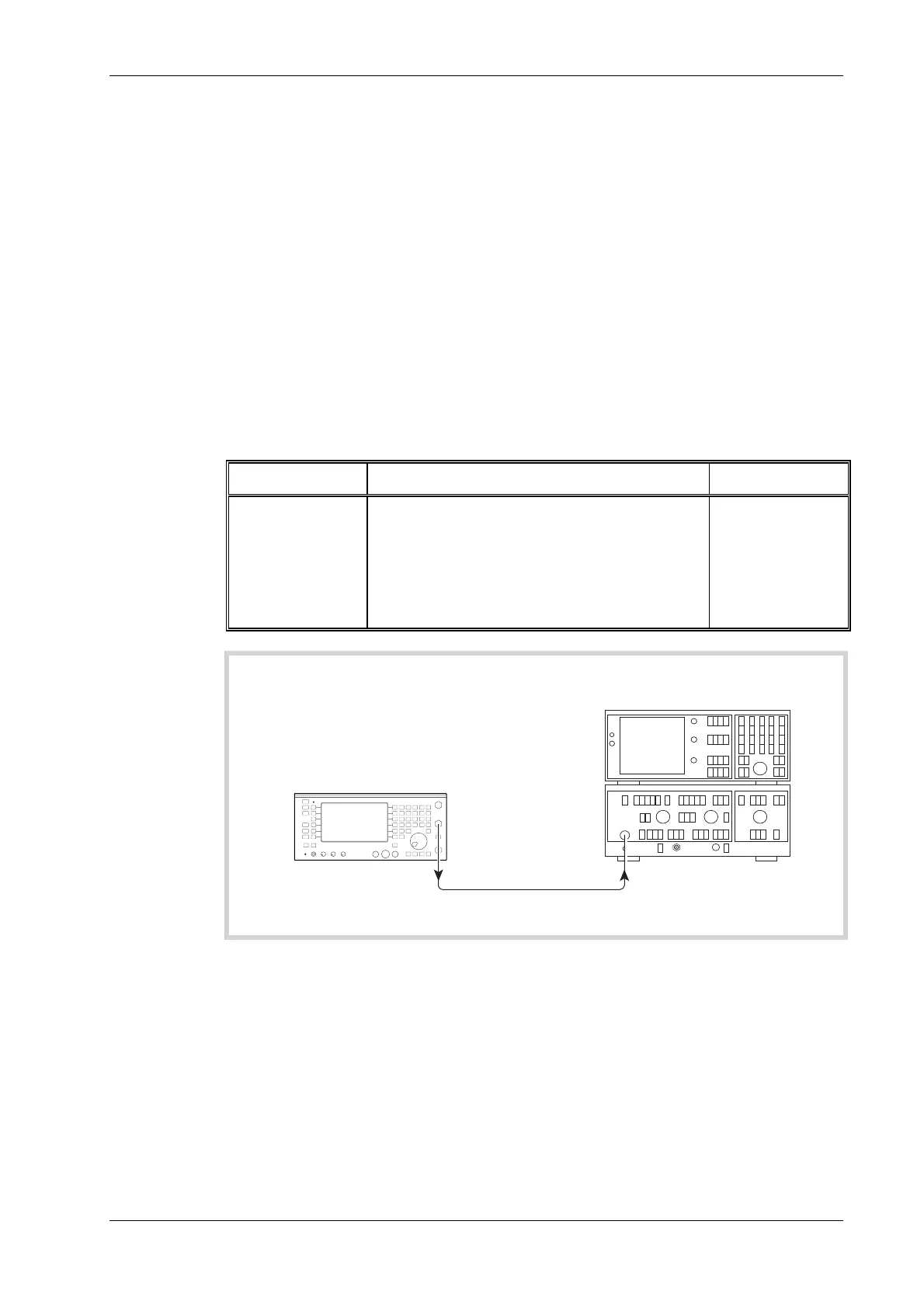
BNC
SOCKET
C6043
UUT
Spectrum analyzer
Fig. 5-5 Carrier harmonics & spurious check
(1) Refer to Results table 5-6 on page 5-39. Connect the Spectrum analyzer to the BNC socket
on the UUT, as shown in Fig. 5-5.
(2) Set the UUT to [Rx TEST], RF IN/OUT [SELECT] BNC output, [RF Gen],
[LEVEL] 0 dBm, [FREQ] 0.4 MHz. All modulation and noise measurements should be
switched OFF.
(3) Tune the Spectrum analyzer to view the harmonics shown in the second harmonic and third
harmonic column of Results table 5-6, checking that they are within the above specification.
(4) Repeat steps (2) and (3) for the remaining frequencies shown in the table.
 Loading...


