ACCEPTANCE TESTING
5-11
(5) Refer to Results table 5-7 on page 5-39. Set the UUT to [Rx TEST], RF IN/OUT [SELECT]
BNC output, [RF Gen], [LEVEL] 0 dBm, [ FREQ] 0.4 MHz.
(6) Use the Spectrum analyzer to check that any spurious signals are < −40 dBc. Repeat for
UUT carrier frequencies of 500 MHz and 1000 MHz. Repeat for a UUT carrier frequency of
650 MHz checking that any spurious signals are < −30 dBc.
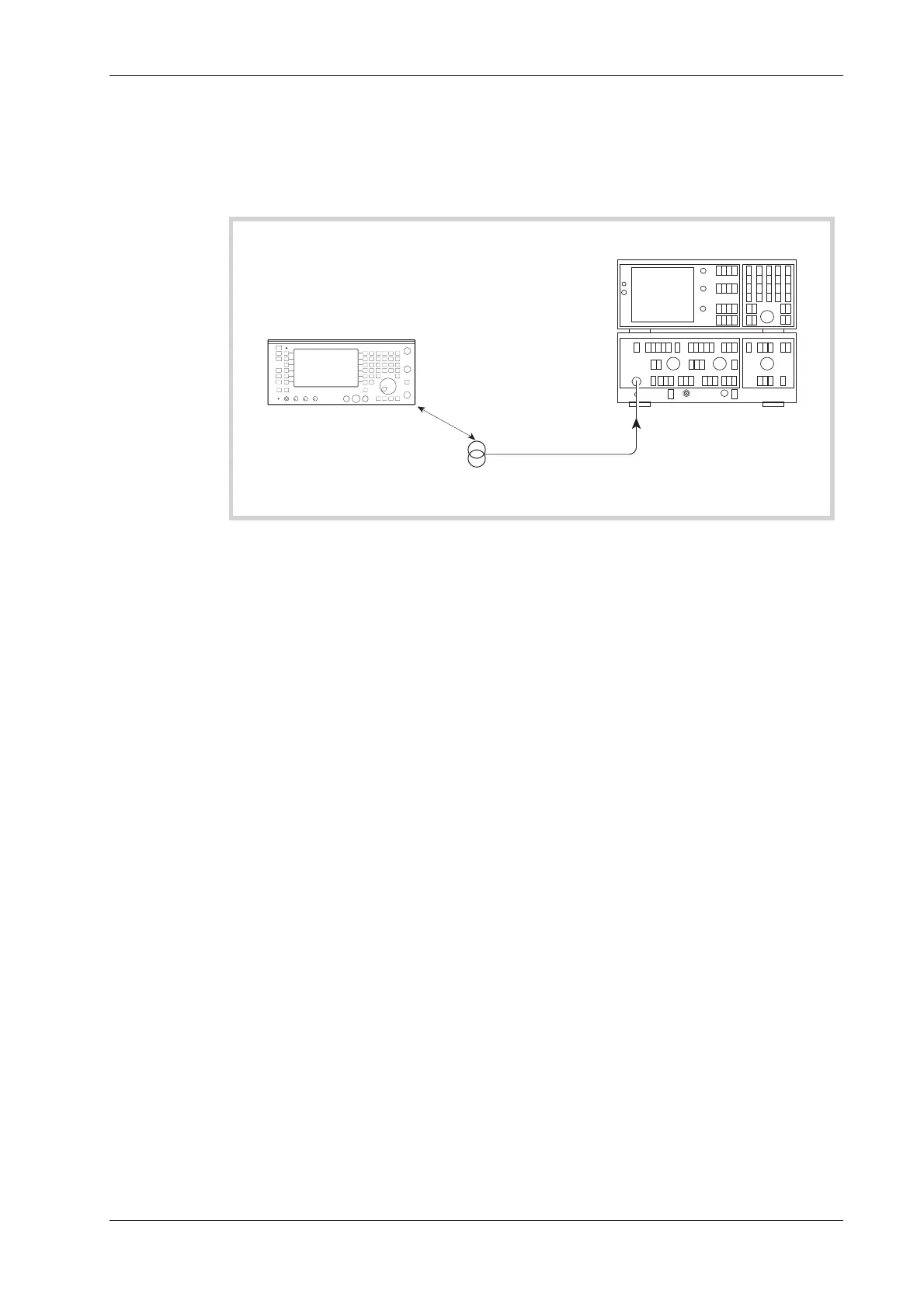
Spectrum analyzer
C6044
25 mm
Two turn loop
25 mm diameter
RF INPUT
UUT
Fig. 5-6 RF carrier leakage check
(7) Refer to Results table 5-8 on page 5-39. Connect the test equipment as shown in Fig. 5-6,
with the 50 Ω load connected to the BNC socket of the UUT.
(8) Set the UUT to [Rx TEST], RF IN/OUT [SELECT] BNC output, [RF Gen],
[LEVEL] −40 dBm, [FREQ] 501.9873 MHz.
(9) Tune the Spectrum analyzer to monitor 501.9873 MHz. Set other Spectrum analyzer
controls to allow the display of signals below −121 dBm (if using the 2383, this can be set to
meter mode).
(10) Hold the loop 25 mm away from the UUT case and check that the level picked up on the
Spectrum analyzer is less than 0.5 µV PD.
(11) To confirm the low residual FM of the UUT, the use of an extremely low-noise FM
demodulator is necessary; this is achieved by using the IFR 2041 Low-noise signal generator
as the local oscillator for the 2305. Connect the test equipment as shown in Fig. 5-7.
 Loading...


