ACCEPTANCE TESTING
5-12
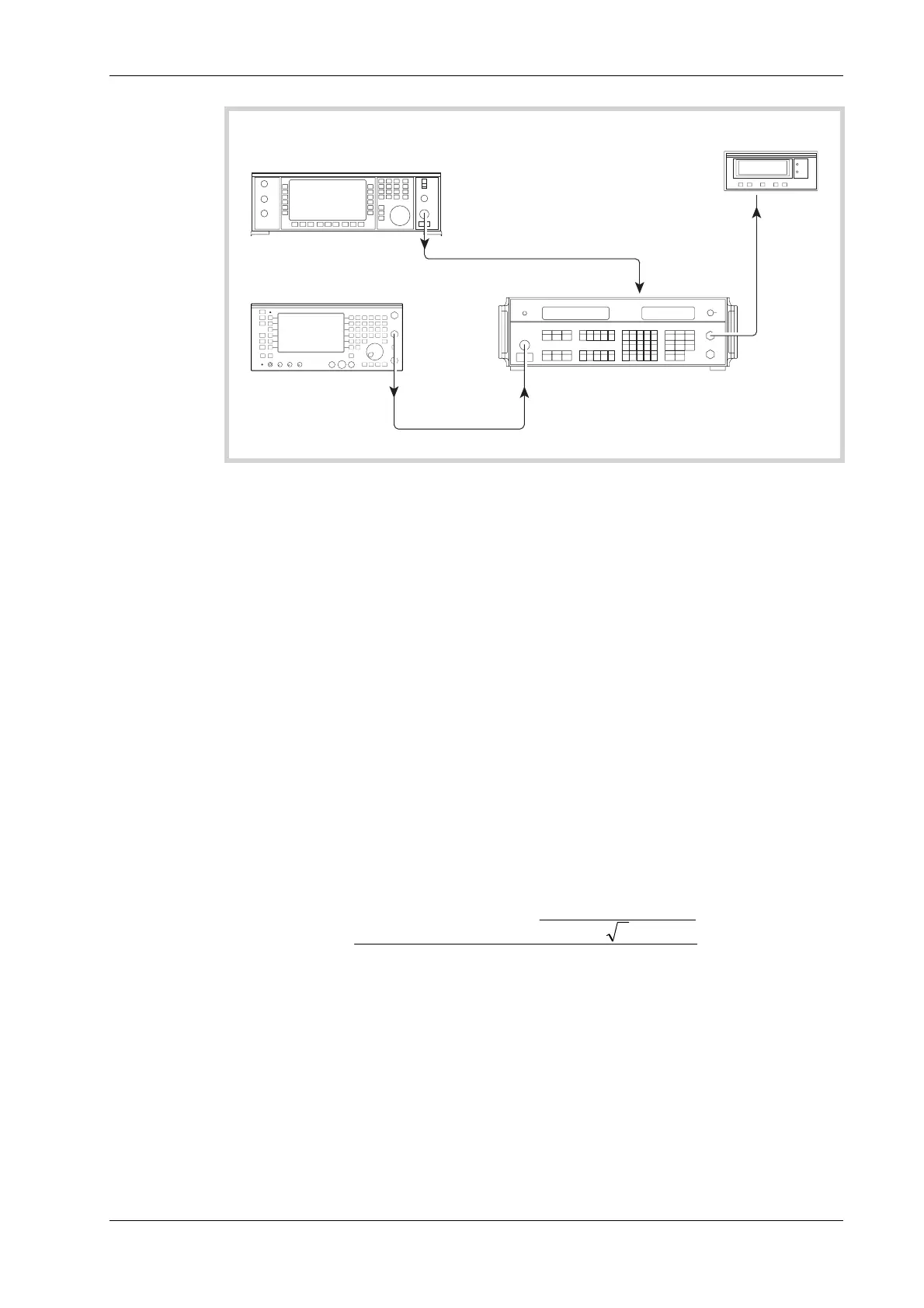
UUT
Signal generator
C6045
RF INPUT
BNC
OUTPUT
RF OUTPUT
EXT LO
INPUT
LF
OUTPUT
Modulation meter
DVM
VOLTMETER
INPUT
TERMINALS
Fig. 5-7 Residual FM checks
(12) Refer to Results table 5-9 on page 5-39. Set the UUT to [Rx TEST], RF IN/OUT [SELECT]
BNC output, [RF Gen], [LEVEL] 0 dBm, [ FREQ], 1000 MHz, [Mod Gen], [Gen1/Gen2],
to select modulation generator 2, and then [LEVEL], 1 kHz. After this key sequence
modulation generator 2 should be providing 1 kHz deviation at 1 kHz modulation rate.
Modulation generator 1 should be OFF.
(13) Set the signal generator into low noise mode 1 and to provide a signal of 55.63889 MHz at
0 dBm.
(14) Set the Modulation meter to measure FM in a 300 Hz to 3.4 kHz bandwidth with noise
averaging on. Select external LO by pressing FREQ TUNE, 0, ENTER. External LO should
now appear in the top left of the modulation window display and the frequency window
should display the IF frequency of 1.5 MHz ±150 kHz. Note the DEVIATION LEVEL (Hz)
displayed on the modulation meter. Set the LF LEVEL control on the front panel of the
modulation meter to the horizontal mark and press HOLD ON/OFF.
(15) Set the DVM to measure AC volts and make a note of the voltage displayed MOD
VOLTAGE (V).
(16) On the UUT press [ON/OFF] to switch modulation generator 2 OFF, then note the
RESIDUAL VOLTAGE (V) displayed on the DVM.
(17) The residual FM in HZ RMS. can now be calculated as follows:-
RESIDUAL FM=
VOLTAGEMOD
LEVELDEVIATION
VOLTAGERESIDUAL
2
×
(18) Set the UUT RF Generator and the local oscillator to the frequencies shown in Results
table 5-9, confirming that the residual FM indicated on the Modulation meter is within the
limits shown in the right hand column.
 Loading...


