INSTALLATION
2-7
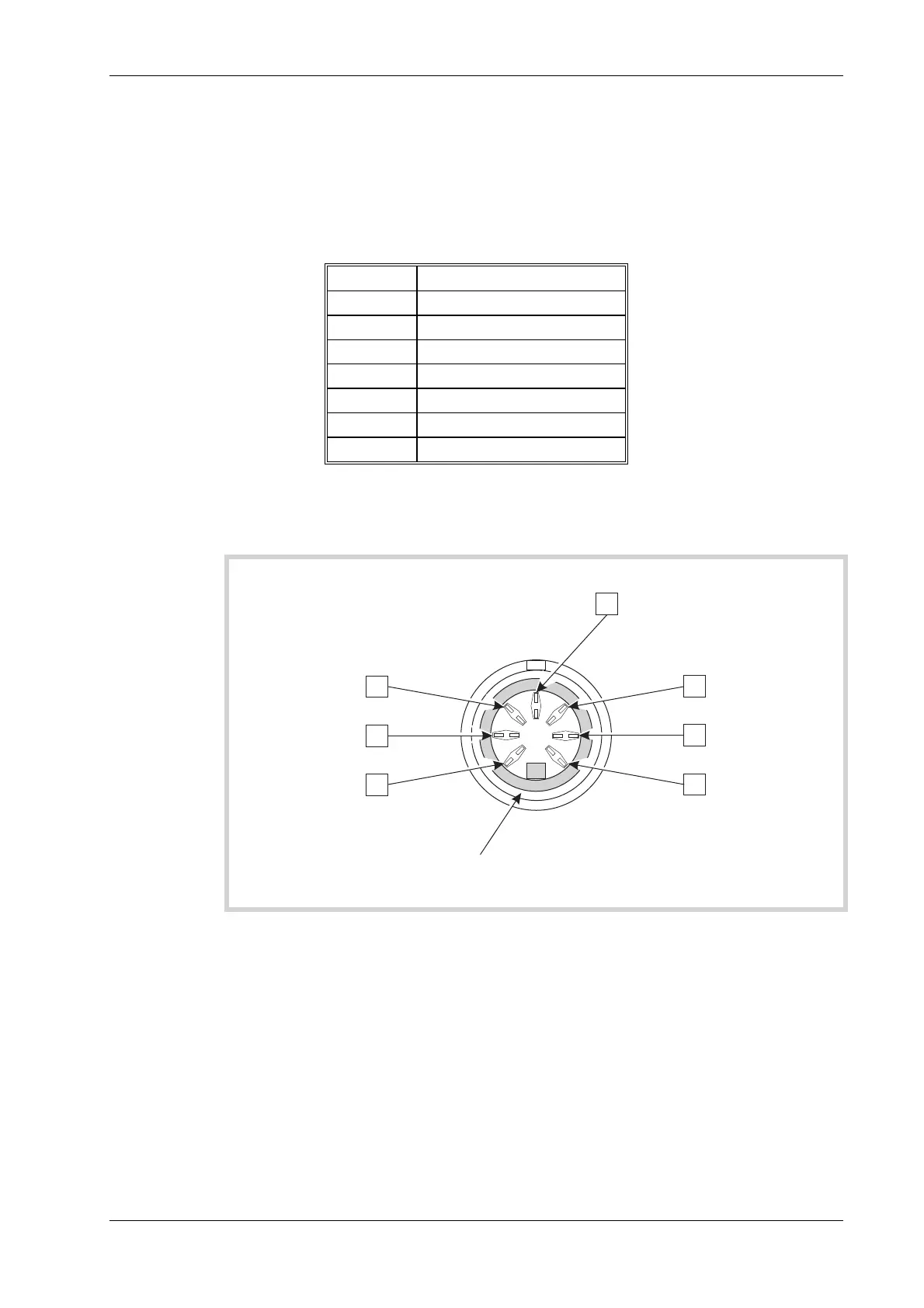
Accessory socket connections
The accessory socket located on the front panel, is of the 7 pin DIN, 45° configuration.
The function of each of the pins on this socket is shown in the following table. The pin numbering
is shown in Fig. 2-2 Accessory in/out socket pin numbers, and is as viewed from the front of the
Service Monitor.
Table 2-1 Accessory socket pin numbering, location and functions.
Din pin No Function
6 Logic
1 Mic input/PTT-logic
4 Forward power
2 12 V DC at approx 100 mA
5 Reverse power
3 Logic
7 Loudspeaker output
The pin numbering of the Accessory socket, as seen from the front of the Service Monitor, is
shown in Fig. 2-2 Accessory in/out socket pin numbers.
C1785
EARTH SHIELD
13
45
2
6
7
Fig. 2-2 Accessory in/out socket pin numbers
The socket is used for connecting dedicated accessories such as microphones with press to talk
switching capabilities.
Selection logic [or data signals] on pins 1,3 and 6 enables the Service Monitor to recognize the
connections of an external accessory. The appropriate pins are at TTL levels and are active low
(L) as shown below: