LOCAL OPERATION
3-94
Accessory port (rear optional)
As well as the parallel printer output, this option also provides an accessory port that allows the
control of external devices by logic control from the instrument. Fig. 3-28, Rear accessory port
socket connections, shows the pin numbering of the socket and Table 3-2,
Rear accessory port
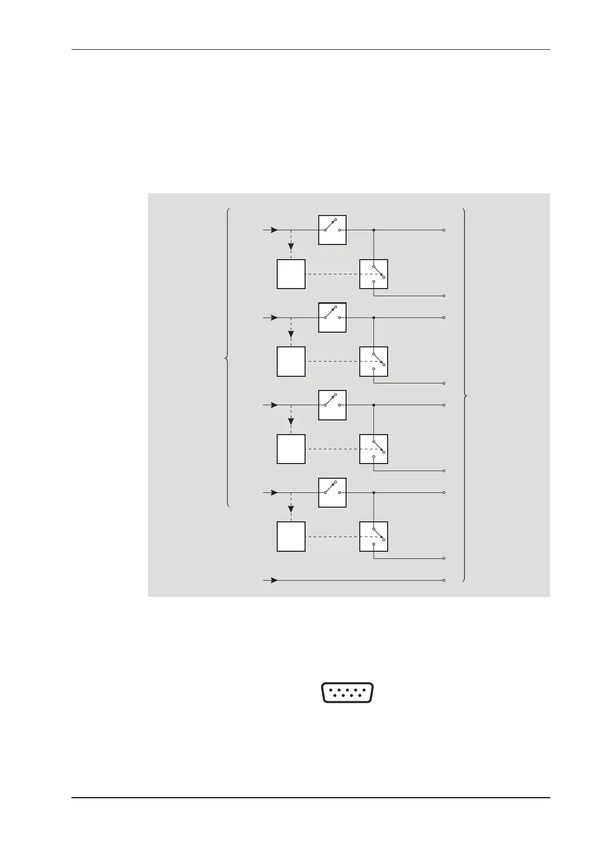
connections, shows the function of the socket connections. Fig. 3-27, Simplified diagram of rear
accessory port switching shows the switching associated with the port.
Switches 1(a) to 1(d) are parts of a multi-pole rocker switch, mounted on the printed circuit board
within the option assembly. By setting these switches, the user has the option of logic level output
on the appropriate pins or of closing contacts between pairs of pins.
C2157
RELAY
RELAY
RELAY
RELAY
LINE 0
SW1(a)
SW1(b)
SW1(c)
SW1(d)
LINE 1
LINE 2
FROM
LOGIC
CIRCUITS
ACCESSORY
PORT
LINE 3
+5V
9
8
7
6
5
4
3
2
1
Fig. 3-27 Simplified diagram of rear accessory port switching
Pin Connections
5
9
1
6
Fig. 3-28 Rear accessory port socket connections (as seen facing panel)