Deployment Guide 129
EXAMPLE 4: CONNECTING HIVEAPS TO HIVEMANAGER
EXAMPLE 4: CONNECTING HIVEAPS TO HIVEMANAGER
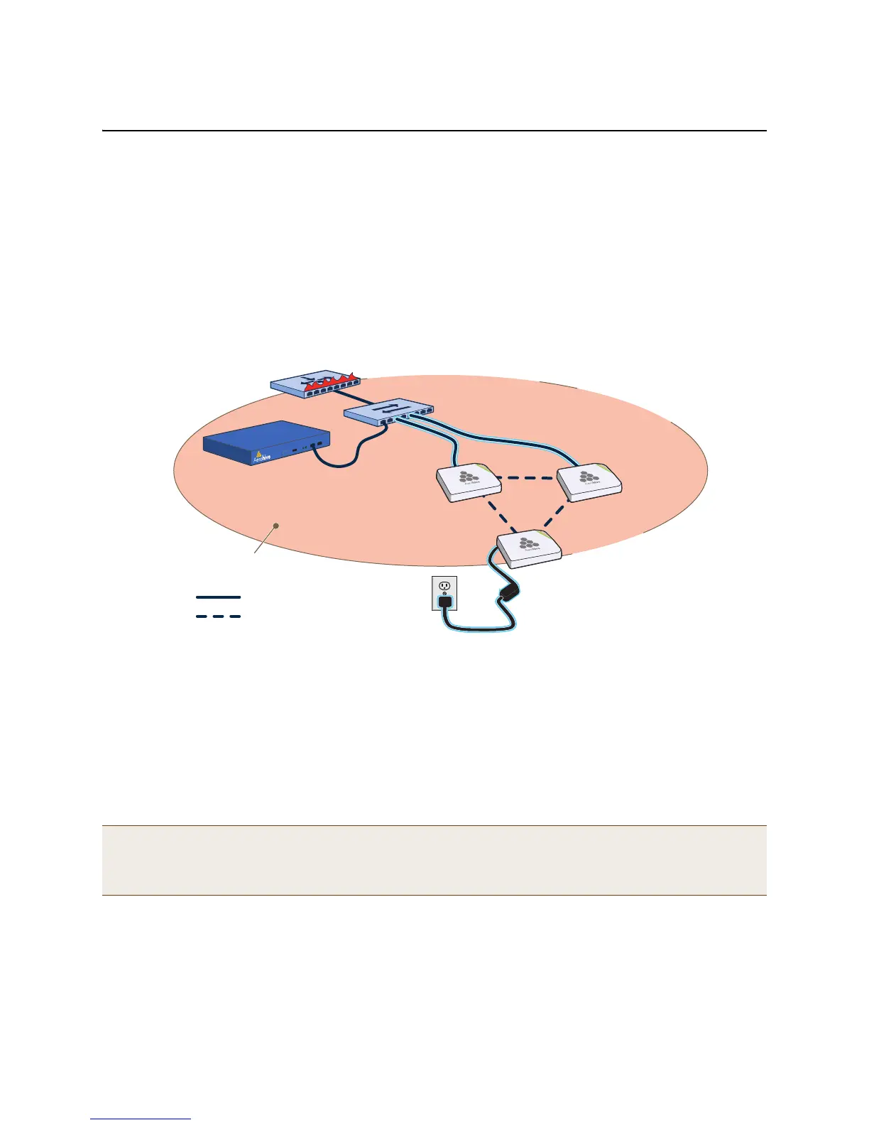
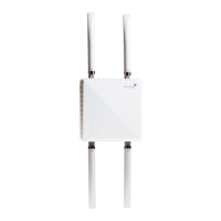
In this example, you set up three HiveAPs for management through HiveManager. Cable two of the HiveAPs—HiveAP1
and HiveAP2—to the network. Run an Ethernet cable from the eth0 port on each HiveAP to a switch so that they are
in the same subnet as the IP address of the MGT interface on HiveManager. (Neither the HiveAP 300 eth1 port nor
the HiveManager LAN port are used in this example.) You can use AC/DC power adaptors to connect them to a
100-240 VAC power source or allow them to obtain power through PoE (Power over Ethernet) from PSE (power
sourcing equipment) on the network. (Both power adaptors and PoE injectors are available from Aerohive as
options.) Place the third HiveAP—HiveAP3—within range of the other two, and use a power adaptor to connect it to
an AC power source. See Figure 3, in which the switch uses PoE to provide power to HiveAPs 1 and 2.
Figure 3 Connecting HiveAPs to the network
By default, the HiveAPs obtain their network settings dynamically from a DHCP server. HiveAP3 reaches the DHCP
server after first forming a wireless link with the other two HiveAPs. (A HiveAP in the position of HiveAP3 is referred
to as a mesh point, and HiveAPs such as HiveAP1 and 2 are called portals.)
Within the framework of the CAPWAP (Control and Provisioning of Wireless Access Points) protocol, HiveAPs act as
CAPWAP clients and HiveManager as a CAPWAP server. Because all devices are in the same subnet in this example,
the clients can broadcast CAPWAP Discovery Request messages to discover and establish a secure connection with
the server automatically. During the connection process, each client proceeds through a series of CAPWAP states,
resulting in the establishment of a secure DTLS (Datagram Transport Layer Security) connection. These states and
the basic events that trigger the client to transition from one state to another are shown in Figure 4 on page 130.
For information about various ways that HiveAPs can form a secure CAPWAP connection with a physical HiveManager
appliance or a HiveManager Virtual Appliance in the same or different subnets, and with HiveManager Online, see
"How HiveAPs Connect to HiveManager" on page 133.
Note: To illustrate all possible CAPWAP states, Figure 4 on page 130 begins by showing a HiveAP and HiveManager
already in the Run state. When a HIveAP first attempts to discover a HiveManager—after the HiveAP has an
IP address for its mgt0 interface and has discovered or has been configured with the HiveManager IP
address—it begins in the Discovery state.
= Wired Link
= Wireless Link
HiveManager
Single Subnet
Layer-2 Broadcasting Domain
Router/Firewall/DHCP Server
Switch/PSE The switch delivers power
to HiveAP1 and HiveAP2
through PoE.
HiveAP1
(Portal)
HiveAP3
(Mesh Point)
HiveAP3 receives power
from a 100-240 VAC outlet.
HiveAP2
(Portal)