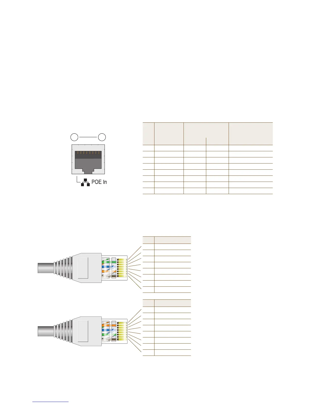
Pin T568A Wire Color
1 White/Green
2 Green
3 White/Orange
4Blue
5 White/Blue
6 Orange
7 White/Brown
8Brown
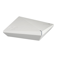
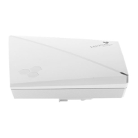
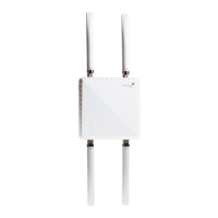
(View of the PoE port
on the HiveAP)
1 8
Pin Numbers
Pin T568B Wire Color
1 White/Orange
2 Orange
3 White/Green
4Blue
5 White/Blue
6 Green
7 White/Brown
8Brown
T568A-Terminated Ethernet Cable
with an RJ-45 Connector
802.3af Alternative A
(Data and Power on
the Same Wires)
802.3af Alternative B
(Data and Power on
Separate Wires)
Pin Data Signal MDI MDI-X MDI or MDI-X
1 Transmit + DC+ DC– – – –
2 Transmit - DC+ DC– – – –
3 Receive + DC– DC+ – – –
4 (unused) – – – – – – DC+
5 (unused) – – – – – – DC+
6 Receive - DC– DC+ – – –
7 (unused) – – – – – – DC–
8 (unused) – – – – – – DC–
MDI = Medium dependent interface for straight-through connections
MDI-X = Medium dependent interface for cross-over (X) connections
The PoE port is auto-sensing and can automatically adjust to transmit and receive data over straight-through or cross-over Ethernet
connections. Likewise, it can automatically adjust to 802.3af Alternative A and B power delivery methods. Furthermore, when the
Alternative A method is used, the PoE port automatically allows for polarity reversals depending on its role as either MDI or MDI-X.
T568B -terminated Ethernet Cable
with an RJ-45 Connector
T568A and T568B are two standard
wiring termination schemes. Note that
the only difference between them is
that the white/green + solid green pair
of wires and the white/orange + solid
orange pair are reversed.
For straight-through Ethernet
cables—using either the T568A or
T568B standard—the eight wires
terminate at the same pins on each
end.
For cross-over Ethernet cables, the
wires terminate at one end according
to the T568A standard and at the
other according to T568B.