104
Chapter 5: Troubleshooting
Return to the troubleshooting flowchart.
To test the cables (16700-series Mainframe)
This test allows you to functionally verify the logic analyzer cable and an Agilent
E5379A probe.
Equipment Required
1 Connect the logic analyzer to the stimulus board.
a Connect an Agilent E5379A 100-pin differential probe to the logic
analyzer cable (also called “Pod”) to be tested.
b Connect the probe input to the stimulus board connector Pod 4.
c Connect the stimulus board power supply output to the stimulus board
power supply connector J82.
d Plug in the stimulus power supply to line power. The green LED DS1
Equipment Critical Specification Recommended Part
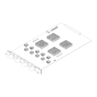
Stimulus Board No Substitute 16760-60001
Artisan Technology Group - Quality Instrumentation ... Guaranteed | (888) 88-SOURCE | www.artisantg.com
 Loading...
