117
Chapter 6: Replacing Assemblies
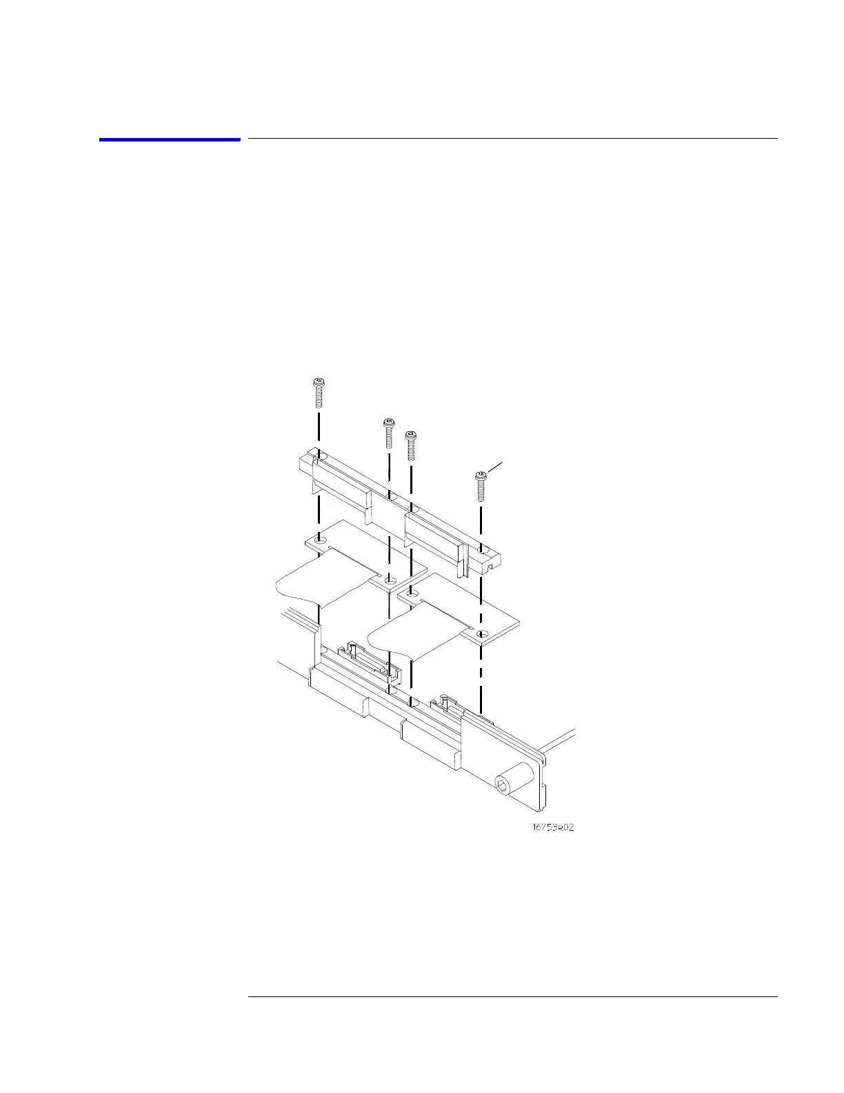
To install the logic analyzer cable
1 Connect the logic analyzer cable to the logic analyzer circuit board.
a Insert the logic analyzer cable to the logic analyzer circuit board.
b Align the logic analyzer cable end connector with the circuit board
cable connector (J1, J2, J3, or J4) and gently apply pressure to seat the
logic analyzer cable onto the circuit board connector.
c Insert the top and bottom logic analyzer cable clamps into the rear
panel.
2 Secure the cable clamp to the rear panel.
a Install the four screws (H5) vertically through the cable clamp into both
the cable clamp and the circuit board.
H4
Artisan Technology Group - Quality Instrumentation ... Guaranteed | (888) 88-SOURCE | www.artisantg.com

 Loading...


