51
Chapter 3: Testing Logic Analyzer Performance
Test Pod 2 in 300 Mb/s Mode
Test Pod 2 in 300 Mb/s Mode
1 Disconnect the E5382A Flying Lead Probe Set from Pod 1 and connect it
to Pod 2 of the logic analyzer. Do not remove the flying leads that are
connected to CLK, CLK, and the data channels.
2 On the 8133A pulse generator, in the PULSE setup for CHANNEL 2, press
the COMP button to return the outputs to normal.
3 Note that the signal on the oscilloscope has moved. Change the
oscilloscope’s horizontal position to 525 ps (or as required) to center the
measured pulse on the oscilloscope display.
4 Verify the DC offset and adjust it if necessary. See page 32.
5 Deskew the oscilloscope if necessary. See page 33.
6 Readjust the pulse width from the pulse generator as measured on the
oscilloscope. See page 35.
7 From the Logic Analysis System main menu, select Setup→My
16950A→Bus/Signal...
8 Scroll to the right and unassign all Pod 1 bits.
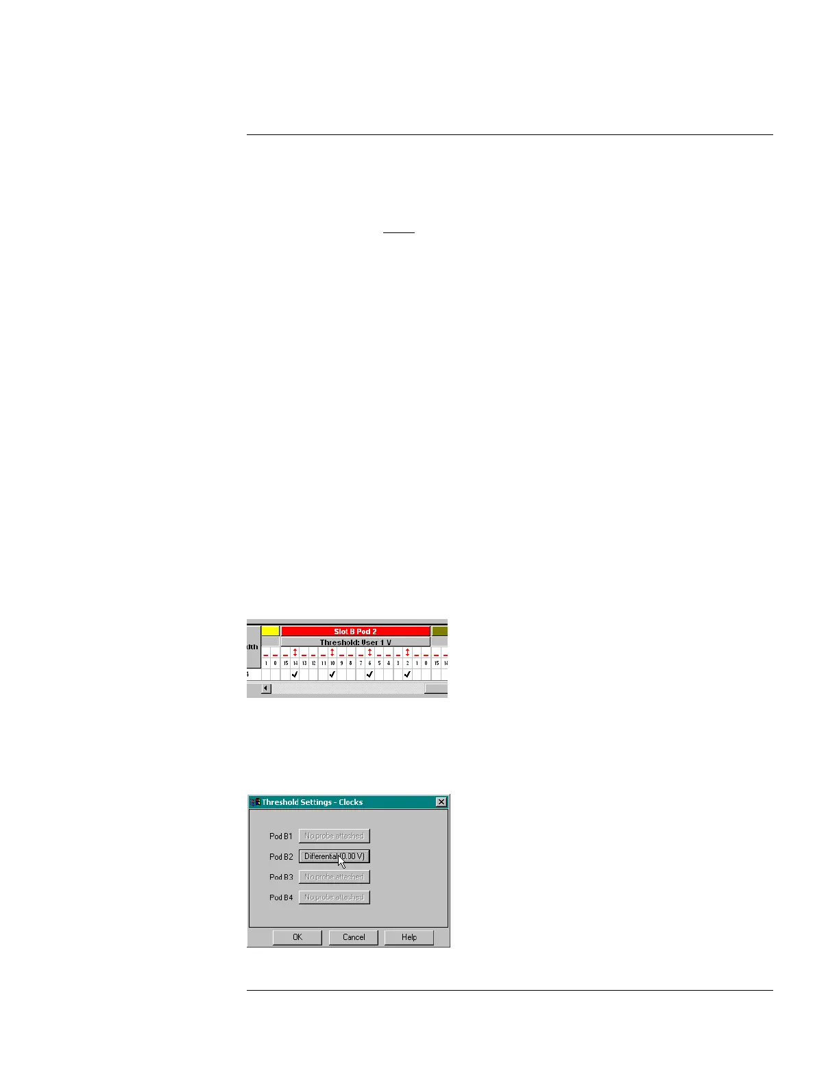
9 Set the Pod 2 threshold to 1 volt (just as you did for Pod 1 on page 40).
10 Assign bits 2, 6, 10, and 14 of Pod 2.
11 Scroll to the left and select the Clock Thresholds button. In the “Threshold
Settings - Clocks” window, select the Pod 2 clock threshold button. The
“Threshold Settings: Clock for Pod 2” window will appear. Set the Clk2
threshold to Differential.
Artisan Technology Group - Quality Instrumentation ... Guaranteed | (888) 88-SOURCE | www.artisantg.com

 Loading...


