23
Chapter 3: Testing Logic Analyzer Performance
Assemble the SMA/Flying Lead Test Connectors
Assemble the SMA/Flying Lead Test Connectors
The SMA/Flying Lead test connectors provide a high-bandwidth connection
between the logic analyzer and the test equipment. The following procedure
explains how to fabricate the four required test connectors.
Materials Required
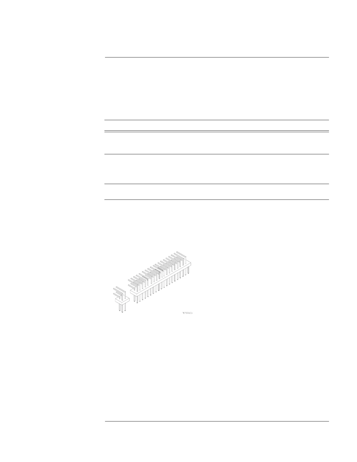
1 Prepare the pin strip header:
a Cut or cleanly break a 2 x 2 section from the pin strip.
Material Critical Specification Recommended Model/Part
SMA Board Mount Connector
(Qty 8)
Johnson 142-0701-801
(see
www.johnsoncomponents.com)
Pin Strip Header
(Qty 1, which will be separated)
.100" X .100" Pin Strip
Header, right angle, pin
length .230", two rows, .120"
solder tails
3M 2380-5121TN or similar 2-
row with 0.1” pin spacing
SMA 50 ohm terminators
(Qty 2)
Minimum bandwidth 2 GHz Johnson 142-0801-866 50 ohm
Dummy Load Plug
SMA m-m adapter
(Qty 4)
Johnson 142-0901-811 SMA
Plug to Plug or similar
Artisan Technology Group - Quality Instrumentation ... Guaranteed | (888) 88-SOURCE | www.artisantg.com

 Loading...


