30
Chapter 3: Testing Logic Analyzer Performance
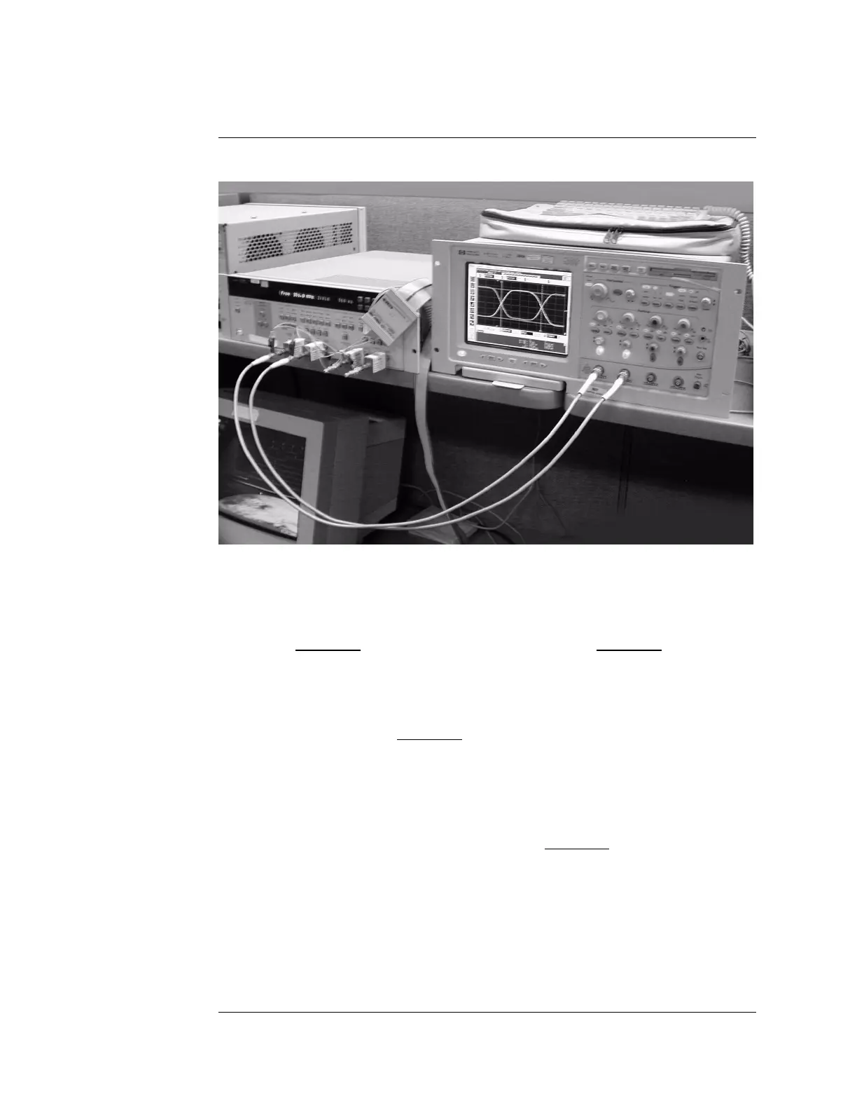
Connect the Test Equipment
Connect the Test Equipment
Connect the 16753/54/55/56A or 16950A Logic Analyzer Pod to the
8133A Pulse Generator
1 Connect a Transition Time Converter (if required—see page 22) to each of
the four outputs of the 8133A pulse generator: Channel 1 OUTPUT,
Channel 1 OUTPUT, Channel 2 OUTPUT, Channel 2 OUTPUT.
2 Connect the two SMA/Flying Lead test connectors (see “Assemble the
SMA/Flying Lead Test Connectors” on page 23) with 50 ohm terminators
to the Transition Time Converters at the 8133A pulse generator Channel 1
OUTPUT and Channel 1 OUTPUT. (If Transition Time Converters are not
required, connect the SMA/Flying Lead test connectors directly to the
pulse generator outputs.)
3 Connect the two SMA/Flying Lead test connectors without 50 ohm
terminators to the Transition Time Converters at the 8133A pulse
generator Channel 2 OUTPUT and Channel 2
OUTPUT. (If Transition Time
Converters are not required, connect the SMA/Flying Lead test connectors
directly to the pulse generator outputs.)
4 Connect an E5382A Flying Lead Probe Set to Pod 1 of the 16753/54/55/
56A or 16950A logic analyzer.
Artisan Technology Group - Quality Instrumentation ... Guaranteed | (888) 88-SOURCE | www.artisantg.com

 Loading...


