31
Chapter 3: Testing Logic Analyzer Performance
Connect the Test Equipment
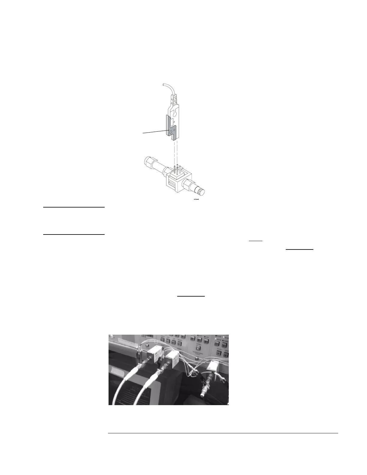
5 Connect the E5382A Flying Lead Probe Set’s CLK lead to the pin strip of
the SMA/Flying Lead connector at the 8133A pulse generator’s Channel 1
OUTPUT.
NOTE: Be sure to use the black ground clip (supplied with the E5382A Flying
Lead Probe Set) and orient the leads so that the black clip is connected to
one of the SMA/Flying Lead connector’s ground pins!
6 Connect the E5382A Flying Lead Probe Set’s CLK lead to the SMA/Flying
Lead connector at the 8133A pulse generator’s Channel 1 OUTPUT. Again,
be sure to use the black ground clip and orient the leads so that the black
clip is connected to ground.
7 Connect the E5382A Flying Lead Probe Set’s bits 2 and 10 to the SMA/
Flying Lead test connector’s pin strip connector at the 8133A pulse
generator’s Channel 2
OUTPUT.
8 Connect the E5382A Flying Lead Probe Set’s bits 6 and 14 to the SMA/
Flying Lead test connector’s pin strip connector at the 8133A pulse
generator’s Channel 2 OUTPUT.
ground clip
Artisan Technology Group - Quality Instrumentation ... Guaranteed | (888) 88-SOURCE | www.artisantg.com

 Loading...


