35
Chapter 3: Testing Logic Analyzer Performance
Connect the Test Equipment
was set to 1 volt in the oscilloscope setup described on page 29.
6 Select Close in the Probe Setup window.
7 Select Close in the Channel Setup window.
Set the 8133A pulse width
1 On the 8133A pulse generator, set the Channel 2 pulse width to 1 ns.
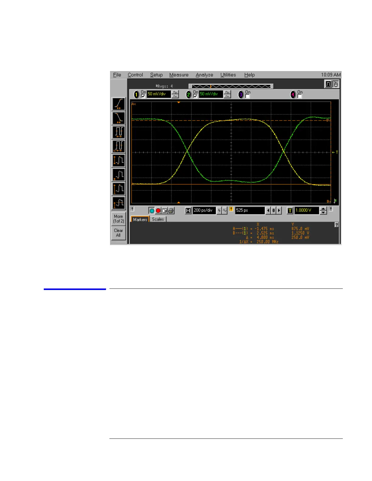
2 Observe the 54845A oscilloscope display. Change the Channel 2 pulse
width of the 8133A pulse generator so that the pulse width measured at 1
volt on the oscilloscope is equal to 1 ns minus the measurement
uncertainty and display resolution of the oscilloscope, further reduced by
35 ps for test margin.
If you are using the 54845A/B oscilloscope, the measurement uncertainty
is ±((0.007% * ∆t) + (full scale/2x memory depth) + 30 ps) = ±30.15 ps.
Add 5 ps for display resolution. Add 35 ps test margin.
1 ns - 30.15 ps - 5 ps - 35 ps = 930 ps. Set the pulse width as measured on
Artisan Technology Group - Quality Instrumentation ... Guaranteed | (888) 88-SOURCE | www.artisantg.com

 Loading...


