Breadboard Module 13
34980A User’s Guide 313
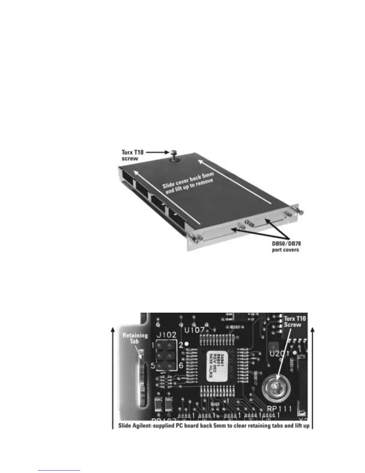
34959A Breadboard Module Disassembly
The module as shipped as shown below. The port covers must be removed
if DB50/78 connectors will be installed for external connections; otherwise
they can remain in place. The top cover provides mechanical integrity and
shielding for the module, and should be attached except when the module
is being configured. To unfasten the top cover, remove the screw with a
Torx T10 driver, slide the cover back 5mm as shown, and lift the cover up.
Reverse this procedure to replace the cover.
34959A Breadboard Module as Shipped
The Agilent- supplied PC board must be removed if you are making
connections to the Analog Buses, in order to solder the necessary relays
(not provided) and lead wires. To remove this PC board, remove the Torx
T10 screw shown, slide the cover back 5mm to clear the two retaining
tabs, and lift the board up. Reverse this procedure to reinstall the board.
Removal of the Agilent-Supplied PC Board

 Loading...


