Breadboard Module 13
34980A User’s Guide 315
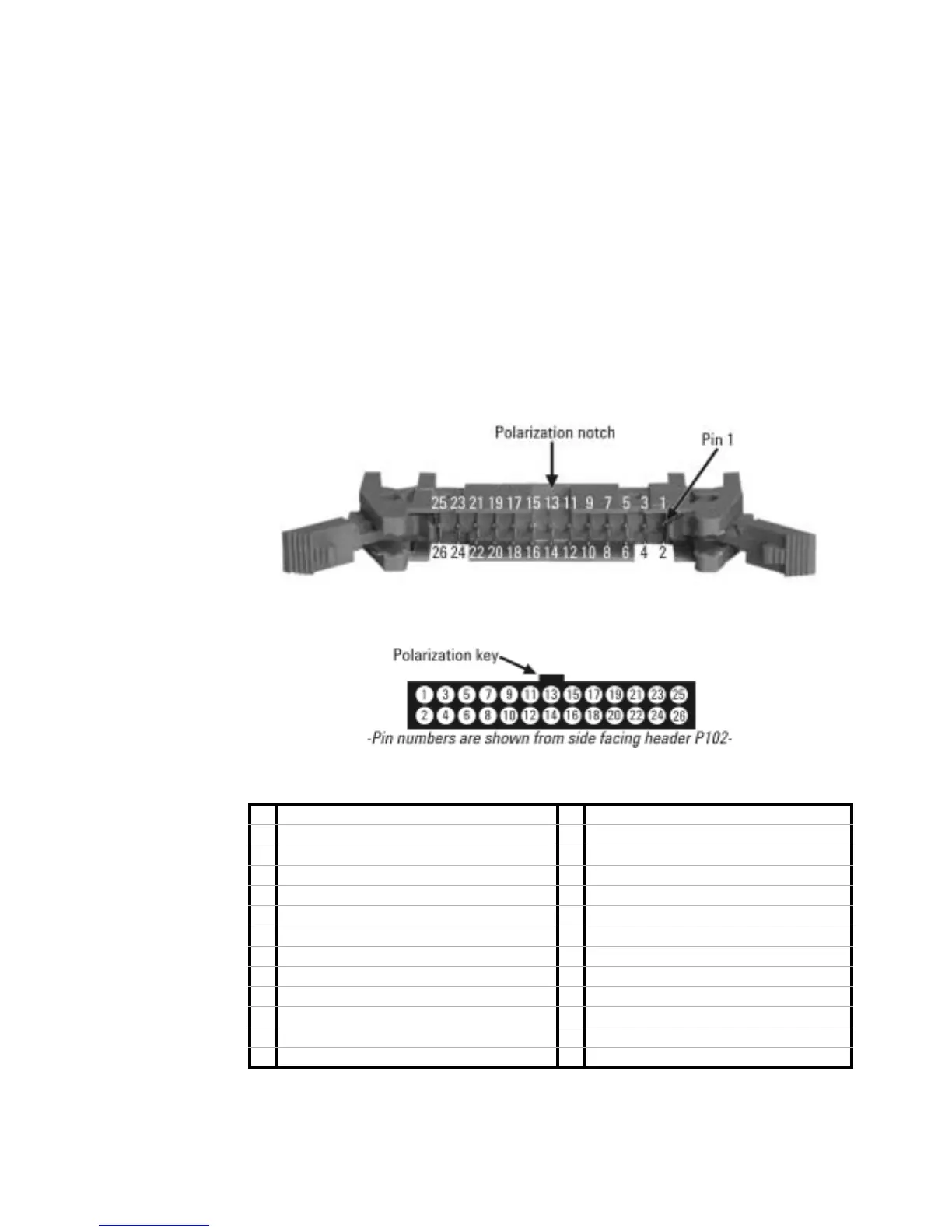
Ribbon Cable Header Pin Assignment Information
The 34959A breadboard is supplied with two ribbon cable headers, which
may be used to access 5V and 12V power, open/close four Analog Bus
channels, open/close up to 28 customer- supplied general- purpose relays,
and utilize two 8- bit banks of digital I/O. The supplied cable headers
(3M Pak 100 series), recommended connectors and their respective pin
assignments are shown below. Pay careful attention to the polarization
notches (indexing keys) on the connectors and headers, to correctly
identify Pin #1.
Supplied 26-Pin Ribbon Cable Header P102 (3M part #3429-5602)
26-pin 0.1” Ribbon Cable Connector (typical keyed connector)
Pin Connection Information for 26-Pin Ribbon Cable Header P102
1 Relay Ground 14 Digital Channel 001; Bit 5
2 Digital Channel 002; Bit 7 15 Digital Channel 001; Bit 4
3 Digital Channel 002; Bit 6 16 +5V power supply
4 Digital Channel 002; Bit 5 17 Digital Channel 001; Bit 3
5 Digital Channel 002; Bit 4 18 Digital Channel 001; Bit 2
6 +5V power supply 19 Digital Channel 001; Bit 1
7 Digital Channel 002; Bit 3 20 Digital Channel 001; Bit 0
8 Digital Channel 002; Bit 2 21 Relay Ground
9 Digital Channel 002; Bit 1 22 Control Line 1: Channel 1 Strobe Line
10 Digital Channel 002; Bit 0 23 Control Line 2: Channel 2 Strobe Line
11 Relay Ground 24 Control Line 3: Read/Write Status Line
12 Digital Channel 001; Bit 7 25 +5V power supply
13 Digital Channel 001; Bit 6 26 Relay Ground