Agilent 708-DS Dissolution Apparatus
Training Manual
Revision A September 2010
P/N: xx-xxxx
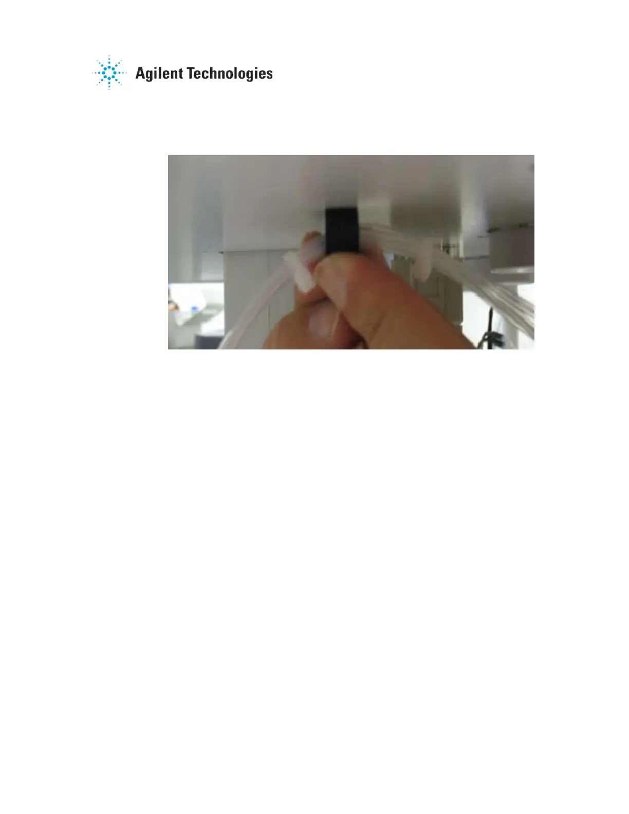
Affix a fastener to the bottom of the drive unit on either side of the center
drive unit lift (see Figure 2-7). Attach the tubing to the clips located toward
the back on the underside of the apparatus drive unit.
Figure 2-7. Sample Tubing Fastener
2.1.9. Shaft / Evaporation Cover / DDM Installation
Once the vessels and manifold have been installed, the remaining
accessories are put into place on the apparatus. Locate the appropriate
pieces to be configured as part of the apparatus: evaporation covers,
DDMs / Cover Aligners / Evaporation Cover Plugs, receptor shafts,
paddle or basket shafts, and shaft locking collars.
Lift the drive unit to its fully raised position. Insert a receptor shaft into
each active spindle location. Place a shaft locking collar on the top of
each shaft and slide it down until it rests on top of the spindle assembly
on top of the drive unit. Slide an evaporation cover over the shafts
(Basket or Paddle) to be installed and attach them to the already installed
receptor shafts at each applicable position.
Locate the DDM assemblies, Cover Aligners, or Evaporation Cover Plugs
to be installed.

 Loading...