Agilent 708-DS Dissolution Apparatus
Training Manual
Revision A September 2010
P/N: xx-xxxx
Move the RPM / Wobble gauge and repeat this procedure for all
applicable vessel positions for each spindle speed desired.
3.1.2. Centering
To verify the shaft of each active position of the apparatus is in the
“center” of each vessel, place the appropriate gauge on the shaft at the
desired vessel position. Locate the gauge on the shaft at the point where
centering is to be verified – ensure the gauge remains on the cylindrical
portion of the vessel.
Agilent’s VK 5010 can be utilized for this measurement and provides a
printout with the distance from the centerline (in mm). The Vessel
Centering Tool included with the 708-DS can be used for a quick “go / no-
go” verification with the help of the Ease Align adapter (QA II Station
accessory).
Move the centering gauge and repeat this procedure for all applicable
vessel positions.
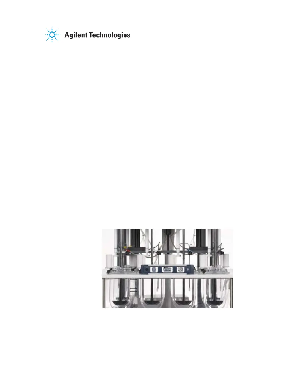
3.1.3. Vessel Table Level
Adjustment of the vessel table level for the unit has been discussed in
Section 2.1.5. Verification of the level can be performed by placing a
digital or bubble level in the middle of the vessel plate.
If a non-quantitative level is used (e.g. torpedo level), the front-to-back
level, as well as the right-to-left level should be verified.
Figure 3-2. Level Verification - Torpedo Level

 Loading...