222 Chapter4
Troubleshooting the Analyzer
Troubleshooting an Inoperative Analyzer
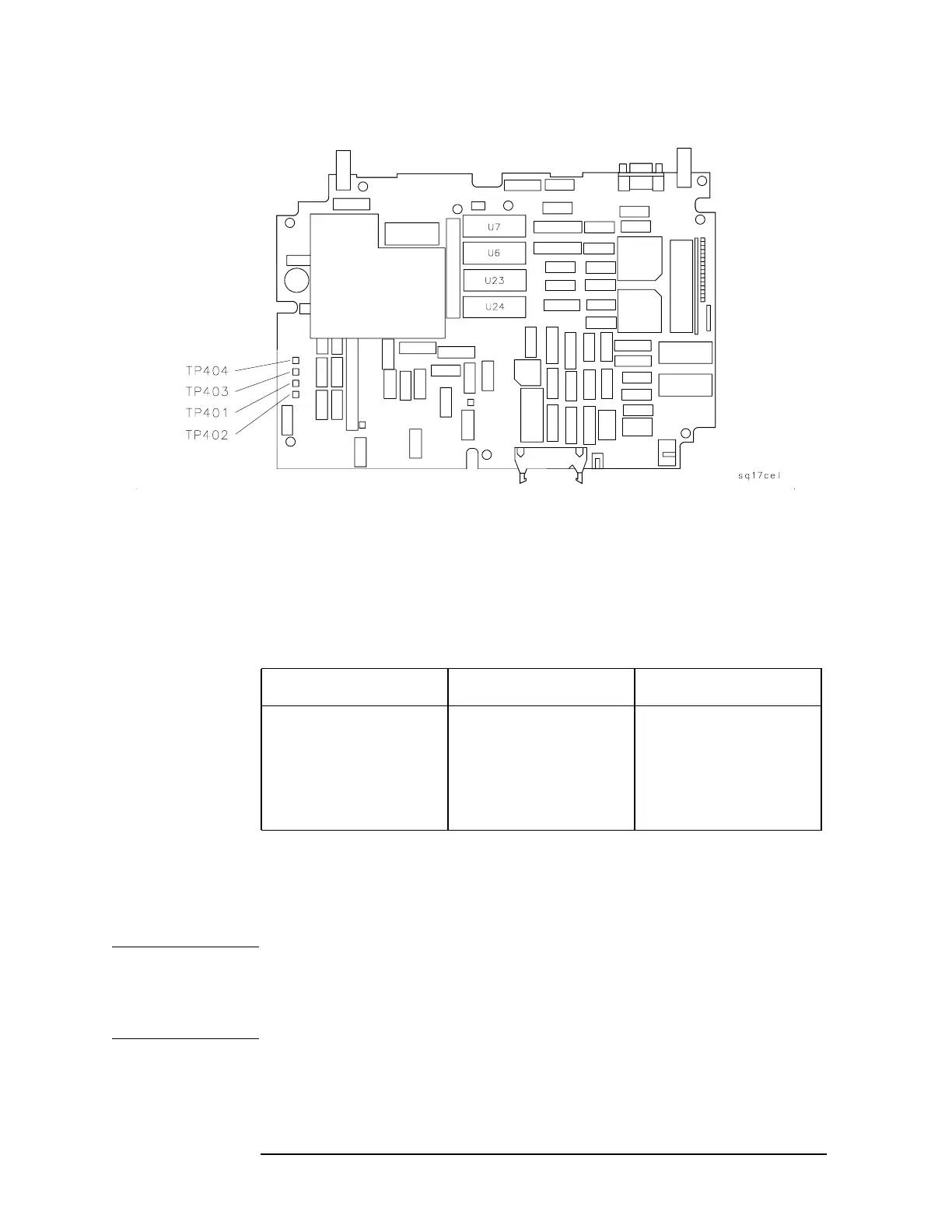
Figure 4-1 A16 Power Supply Test Point Location
3. Turn the analyzer
LINE switch to ON.
4. Locate the power supply test point using Figure 4-1. Check the
supply voltages as indicated in Table 4-2. Be sure the voltage
readings are within the limits shown in Table 4-2.
5. Repeat step 4 for each power supply listed in Table 4-2.
If the line fuse has blown
If the instrument was set up correctly, and the line fuse still blows,
suspect that the power supply is defective.
CAUTION The A8 power supply assembly is a switching power-supply and does
not operate normally without a load on the dc power-supply outputs. Do
not attempt to operate the power supply out of the instrument. Damage
to the power supply may occur.
Table 4-2 Power Supply Tolerances
Power Supply Test Point Specification
+5.1 V A16TP403 +5.0 to +5.25 Vdc
+12.0 V A16TP404 +11.1 to +12.8 Vdc
+15.0 V A16TP401 +14.7 to +15.25 Vdc
−15.0 V A16TP402 −14.7 to −15.25 Vdc

 Loading...
