Chapter 4 229
Troubleshooting the Analyzer
Troubleshooting the A2 Display Assembly
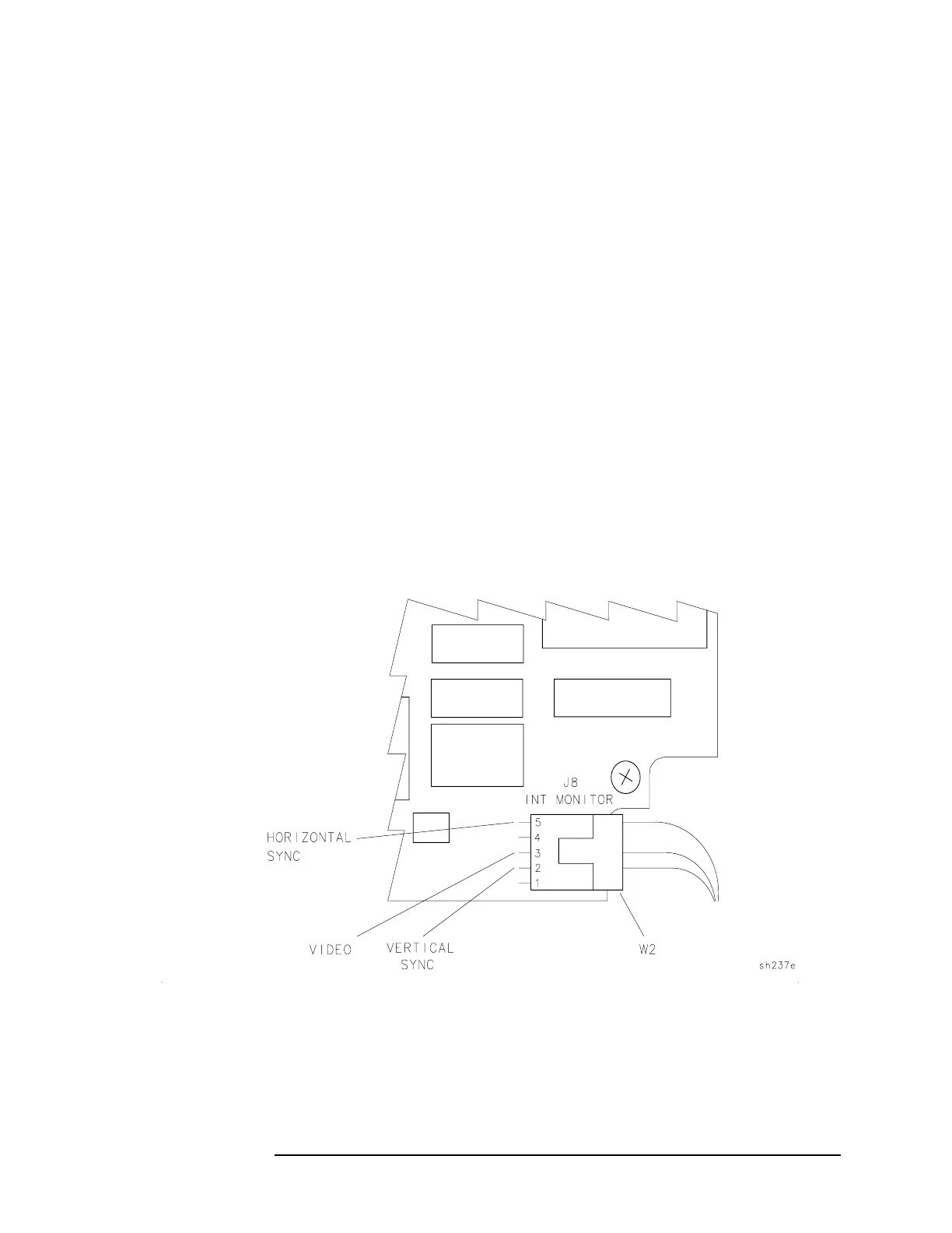
• Refer to Figure 4-4 for the location of the test points and check
the following signals at A16J8 pins, using an oscilloscope.
❏ Check for a 60 Hz TTL signal with a pulse width of
approximately 0.2 ms and a repetition rate of approximately
18 ms at pin 2, vertical sync signal.
❏ Check for an approximately 2.5 V pk-pk video signal at pin 3,
video signal.
❏ Check for a 15.75 kHz TTL signal with a pulse width of
approximately 10 µs and a repetition rate of approximately
64 µs at pin 5, horizontal sync signal.
If the video, horizontal, and vertical signals are missing, but the
+12 V supply voltage is present, continue with step 3.
3. Check the +12 Vdc power supplied to the A2 display. There is a
separate 12 V supply for the display assembly. This supply can be
checked at the output connector, A8J6, located on the right side of
the A8 power supply. Refer to Figure 4-3. If there is a failure, check
the continuity of the cable assembly W51 supplying the display, and
the integrity of the power supply using the procedures in this
chapter.
Figure 4-4 A16J8 Display Signal Output Pins
 Loading...


