320 Chapter7
Replacing Major Assemblies
A7 Analog Interface Assembly
Replacement
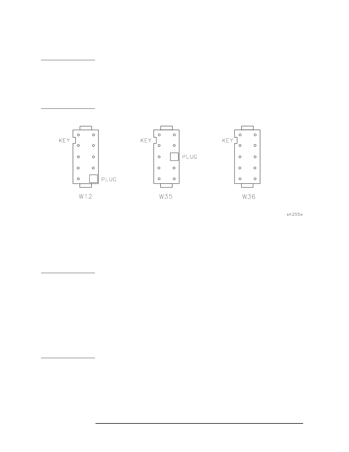
CAUTION Serious instrument damage will result if any wire connector is not
installed correctly. A connector can be installed backwards or in the
wrong position. Inspect each connector and make sure it is not damaged
or missing a key plug. Also inspect the A7 assembly for bent connector
pins. Incorrect connector installation is most likely to occur with the
connectors on W12, W35 and W36. See Figure 7-10.
Figure 7-10 End View of Connectors for W12, W35, and W36
1. Lower the A7 assembly part way into the A7 slot and connect W12,
W13, W34, W35, W36, and W51 (3) to the A7 assembly.
2. If your 8590L, 8591C, or 8591E has an A7A1 Tracking Generator
Control assembly, you will need to reconnect the SMA cables to it as
you lower the A7 assembly into the instrument.
NOTE To ensure proper installation of the A7 assembly, perform the following:
a. Arrange all wiring so that the wires do not press against the A7
assembly.
b. Align the two tabs on the bottom of the A7 assembly with the slots
on the instrument chassis.
c. Avoid bending the pins on the A15 motherboard connector while
positioning the A7 assembly.
d. Align the A7 Analog Interface assembly connector with the A15
motherboard connector carefully.

 Loading...


