Chapter 2 59
Making Adjustments
6. Cal Attenuator Error
Procedure
The accuracy of the amplitude control attenuator is critical to the
proper calibration of the instrument; therefore, this procedure must be
carefully and accurately performed.
1. Turn the analyzer
LINE switch to OFF. Remove the instrument cover
assembly.
2. Turn the analyzer LINE switch to ON.
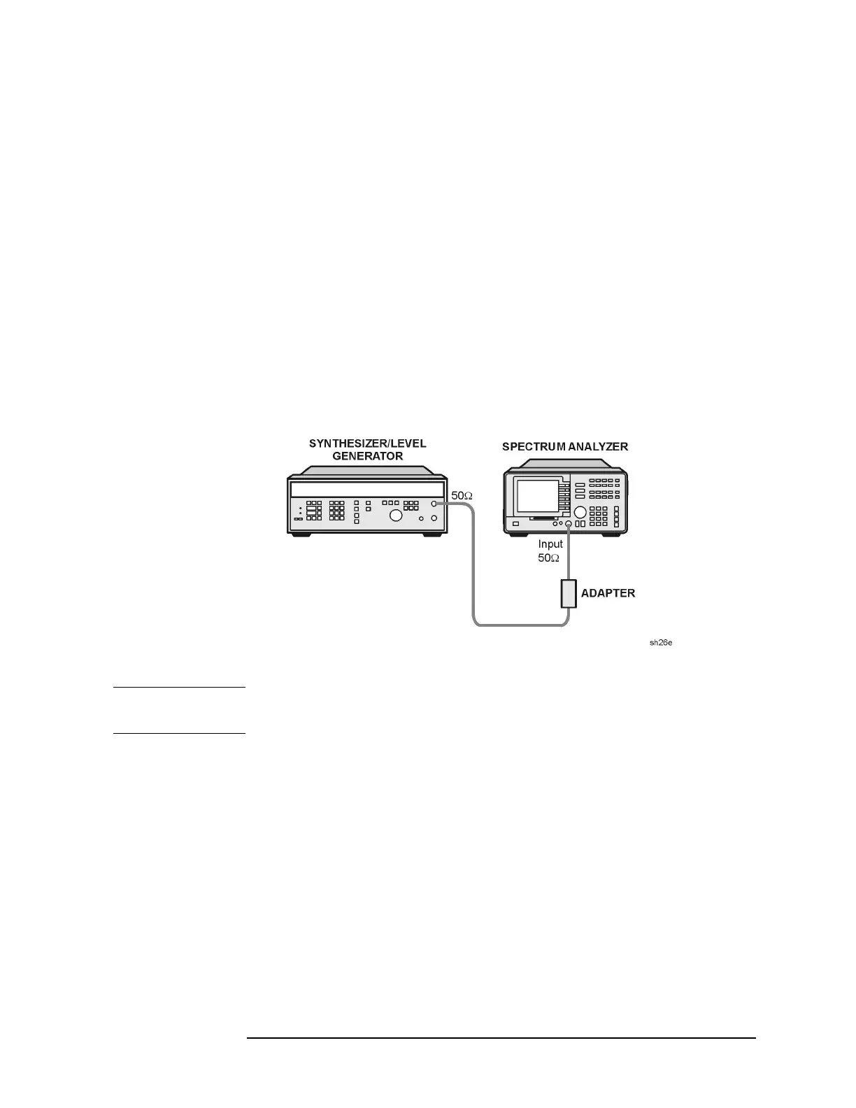
3. Connect the 50 Ω output of the synthesizer/level generator to the
analyzer INPUT 50 Ω. See Figure 2-10.
75 Ω input: Connect the 75 Ω output of the synthesizer/level
generator to the analyzer INPUT 75 Ω.
Figure 2-10 Cal Attenuator Error Correction Setup
CAUTION Use only 75 Ω cables, connectors, or adapters on instruments equipped
with 75 Ω inputs or damage to the input connectors will occur.
4. Set the frequency of the synthesizer/level generator to 25 MHz and
the output to −19 dBm.
5. To turn the amplitude attenuator correction constants off, press the
following analyzer keys.
PRESET
CAL, More 1 of 4
CORRECT ON OFF (OFF)

 Loading...


